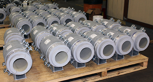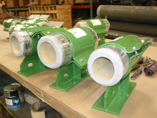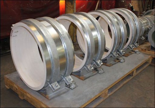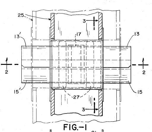
Catalog Model or Custom Design: When a Standard Insulated Support Won’t Work

November 9, 2026

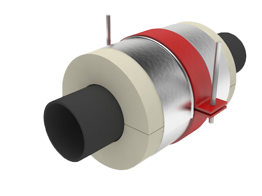
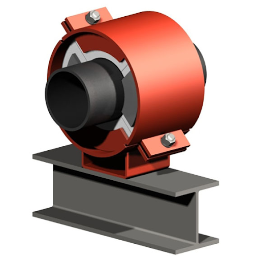
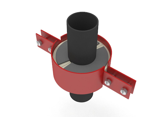
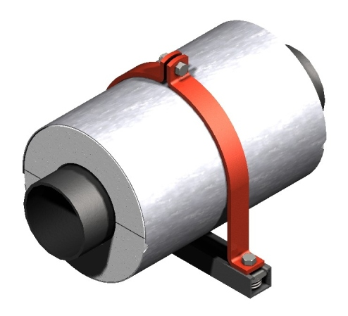
When a catalog doesn’t show an exact match for a support point, it’s easy to assume the job needs a custom design; often it doesn’t. Pipe Shields’ standard series cover a wide range of pipe sizes, temperatures, and support arrangements, and each model has published limits that show where standard ends and engineering review begins. This article covers what the standard series includes, the conditions that call for custom engineering, and how custom pre-insulated supports are designed at Pipe Shields and its parent company, Piping Technology & Products (PT&P). 
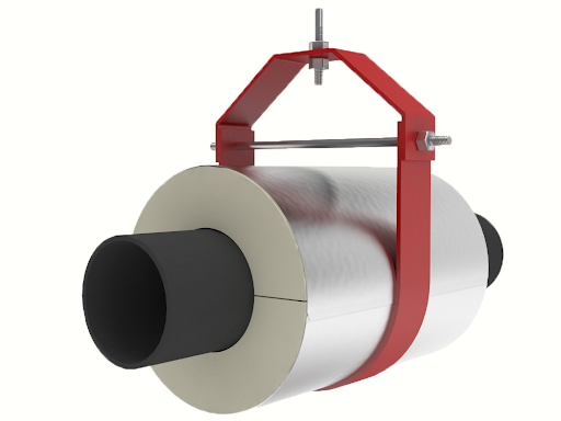
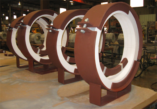
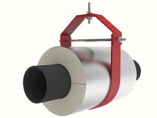
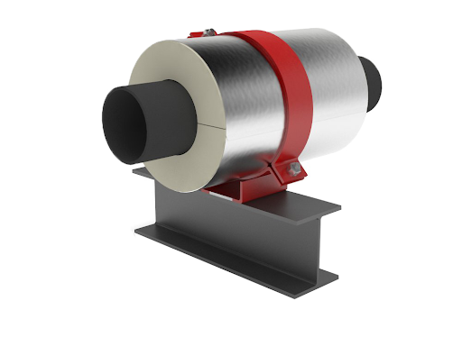
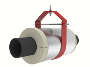
A1000 insulated pipe support
A1000 Insulated Pipe Support

What Our Standard Series Covers

Each Pipe Shields series is built around how the pipe is held:

  • A-series, Commercial and Light Industrial: supports for flat surfaces, pipe rolls, and clevis hangers. A1000–A4000 cover 1/2″ to 24″ pipe, A5000–A8400 cover 2-1/2″ up to 42″, and A9000 is a heavy-duty support for rod hangers, 1/2″ to 24″.
  • B-series, Base Mounted: B1000–B8300 supports built to sit on a flat surface, including sliding, guided, and laterally restrained models.
  • C-series, Pipe Anchors: welded, friction, and positive anchors from 1/2″ to 42″.
  • D-series, Hanger Type: 2-bolt hangers from 1/2″ to 42″, and 2-rod hangers, including models for tight overhead clearances.
  • E-series, Insulated Pipe Riser Clamps: clamps for vertical risers.
  • G-series, Pipe Clamps and Guides: light-duty and heavy-duty guides that mount on standard 1-5/8″ framing channel.
  • PT&P Hot Shoes and Cold Shoes: high-temperature supports usable up to 1400°F, and cryogenic supports.

Each model also carries its own published limits. The A4000, for example, is rated by pipe size for flat-surface, pipe-roll, and clevis-hanger installation. Its standard calcium silicate insulation covers +40°F to +1200°F, and the cryogenic urethane version covers -275°F to +275°F. Load ratings are reduced at 500°F and above by a published temperature factor, and the maximum allowable travel on a pipe roll is set by the support’s dimensions.

Where the Catalog Hands You to the Factory

Beyond those limits, the factory takes over. On the A4000, temperatures up to 1800°F are available on request, and other dimensions, temperatures, and loads go to the factory for review. PT&P’s high-temperature Hot Shoes work the same way: temperatures outside the standard range are handled with the factory, and special requirements such as mill test reports, material certification, or non-standard materials must be specified before the order is placed.

That gives a simple test. When the pipe size, temperature, load, and movement all fall within the published limits for the configuration you need, a catalog model applies. When any one of them falls outside, the application needs a factory review.

Conditions That Call for Custom Engineering

PT&P adapts its standard products to a project in five main areas:

  • Dimensions: almost all products can be resized to meet specific requirements.
  • Load: unusual loads are handled with custom-engineered solutions, checked with in-house finite element analysis (FEA).
  • Travel and movement: custom spring supports and expansion joints are designed for unusual travel requirements.
  • Materials: a wide range is available, including superalloys and thin-gauge material.
  • Finishes: galvanized, painted, neoprene, and paint over galvanized.

For pre-insulated supports, temperature adds another layer. Insulating a support is harder than insulating the pipe itself, because the insulation under the support has to carry the pipe’s load, and insulation’s thermal efficiency generally falls as its compressive strength rises. A pre-insulated support design has to balance those two properties against the temperature limits, the energy to be dissipated, condensation control, exposed-surface temperatures, insulation life, cost, and the space available for the support. 

💡 Key Insight: In a pre-insulated support, the insulation carries the load, so every design has to balance compressive strength against thermal performance.

How the Custom Design Process Works

Custom pre-insulated supports are developed using a combination of FEA, thermal analysis, and material engineering. PT&P runs its FEA in ANSYS and pairs it with in-house manufacturing and testing, so a design can be checked at extreme loads and temperatures, such as a custom pipe clamp analyzed for service at 1015°F.

A custom job can start from either side:

  • Reviewing an existing design: on an LNG project, an EPC customer’s cryogenic support design was checked with FEA and thermal analysis, then put through a cryogenic test. The customer revised the design based on the results.
  • Selecting and sizing the insulation: on a chilled water line, PT&P offered insulation options and, once the customer chose one, calculated the required thickness.

Design calculations for Hot Shoes and Cold Shoes are available for review on request by the purchaser or end user. PT&P’s engineering and design services also produce 3D models for interference checks and work with plant design software such as Intergraph SupportModeler, Microstation, Intergraph PDS, and SmartPlant.

Custom work also scales to full projects. For an ammonia project in Louisiana, PT&P custom-designed 98 insulated pipe supports for both cryogenic and high-temperature lines, with standard QC and dimensional tests performed before shipment.

Check the Catalog First

Start with the series that matches how the pipe is held, then compare your pipe size, temperature, load, and movement with the published limits for that model. If all of them fall inside, the catalog model applies. If one falls outside, bring Pipe Shields in at that point, before a support is designed in-house.

Not sure whether your application is a catalog fit? Connect with our team and schedule time with an engineer to review your support point. Once the requirements are set, request a quote. 

💡 Engineering Takeaway: Compare pipe size, temperature, load, and movement with the model’s published limits before deciding a support needs custom engineering.

Frequently Asked Questions

How do I know if a standard Pipe Shields model will work?
Match the series to how the pipe is held, then check that your pipe size, temperature, load, and movement fall within the published limits for that model. If any one falls outside, contact the factory.

What conditions require a custom design?
Requirements outside the published ratings, such as other dimensions, temperatures, or loads, along with special materials or non-standard finishes.

Can a standard model be modified instead of fully custom designed?
Yes. PT&P states that almost all of its products can be resized to meet specific requirements, and the A4000 page lists temperatures up to 1800°F as available upon request.

Can Pipe Shields review a support design we have already developed?
Yes. On an LNG project, PT&P reviewed an EPC customer’s cryogenic support design using FEA and thermal analysis, ran a cryogenic test, and the customer revised the design based on the results


Read More
Heat Tracing at Insulated Pipe Supports: Plan the Grooves Before Ordering

October 29, 2026

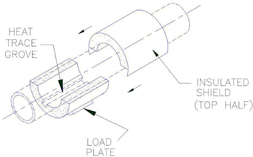
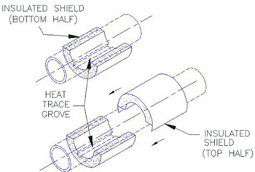
On a heat-traced line, the tracing has to pass every support point on the line. Pipe Shields supplies insulated pipe supports with grooves for heat tracing, so the tracing cable sits inside the support instead of being routed around it. The number and location of the grooves vary by support and are set on the design drawings. This article explains how the grooves work and what to include in your RFQ so the grooves are built in. 

Heat trace groove installation drawing
Heat-trace groove installation drawing

Heat Trace Grooves Are Built Into the Support

Pipe Shields handles heat tracing at the design stage. Each support can be built with one or more grooves in the shield, and the tracing cable is positioned inside the groove when the support is installed. Pipe Shields has supplied many insulated pipe supports with heat trace grooves, and adding them can be done readily and economically.

The grooves are made to the tracing details sent with the order. A support ordered with those details arrives with the grooves in place. A support ordered without them is built without grooves. 

💡 Engineering Takeaway: Check groove positions at every support tag. A matching groove count does not prove alignment.

How Heat Trace Grooves Work at Support Points

Pipe Shields’ installation instructions set out three rules for supports with heat trace grooves. The number and location of the grooves can vary from one support to the next. The design drawings show the exact number and location for each support. During installation, the heat tracing cable must be positioned inside the groove of the shield.

If you’re not sure whether the model you’re specifying can take grooves, confirm with Pipe Shields before ordering.

Heat tracing design

When Heat Tracing Is Left Out of the Support Design

If the tracing details aren’t in the order, the support arrives without a groove. Pipe Shields’ installation instructions cover one method only: a tracing cable seated in a designed groove, at the location shown on the drawings. They give no method for routing tracing around a support that has no groove.

If the supports on site don’t match your tracing layout, check with Pipe Shields before making any change in the field.

How to Specify Heat Tracing in Your RFQ

Every pre-insulated support order starts with six parameters, covered in what information you need to order a pre-insulated pipe support:

  1. Pipe size
  2. Service temperature
  3. Insulation thickness
  4. Load
  5. Support configuration
  6. Expected movement

For a heat-traced line, Pipe Shields asks for four more details:

  • Number of heat tracing lines
  • Size of the heat tracing
  • Configuration of the heat tracing
  • Orientation of the heat tracing

Pipe Shields’ installation instructions refer to heat tracing cable. If your line uses tracer tubing instead, state that in the RFQ and confirm the groove arrangement with Pipe Shields.

Coordinate Heat Tracing Before Ordering Supports

A pre-insulated support design already balances several factors: the temperature limits the support must handle, the energy it must dissipate, preventing condensation that would cause corrosion, keeping exposed surfaces below the maximum temperature allowed by plant safety, and the space available for the support. Sending the tracing details with your RFQ means the grooves are designed alongside these factors and shown on the drawings before installation begins.

Need to confirm a traced support point? Contact us and schedule time with an engineer. Once your tracing details are set, request a quote.

Frequently Asked Questions

Q: Can heat-trace lines be accommodated in Pipe Shields supports?

A: Yes. Pipe Shields can add grooves to accommodate heat tracing. The company has supplied many supports with heat-trace grooves and can add them readily and economically. See the heat-trace FAQ.

Q: What information is needed to add heat-trace grooves?

A: Provide the number, size, configuration and orientation of the heat-tracing lines when requesting a quote.

Q: Do all Pipe Shields supports come with heat-trace grooves?

A: Heat-trace grooves are added based on the customer’s requirements. Provide the tracing details when ordering so Pipe Shields can determine the appropriate configuration for the selected support.

Read More

Pre-Insulated Pipe Support Materials: Detailed Guide

October 29, 2026

Scope

This resource covers the load-bearing insulation materials used in Pipe Shields pre-insulated pipe supports: calcium silicate, polyurethane foam, Foamglas®, and Super Fire Temp. It defines:

  • the function of support insulation
  • the properties and service temperature range of each material
  • the components of a pre-insulated support assembly

Combined, the four materials cover service temperatures from –450°F to +1700°F. 

Pre insulated pipe supports

Function of Support Insulation

A pre-insulated pipe support places load-bearing insulation at the point where the pipe meets the support. The insulation serves two functions: it limits heat transfer at the support and carries the pipe load.

Standard pipe insulation is not designed to carry load. At the support point, insulation is compressed between the pipe and the supporting structure and must resist crushing under the pipe weight.  

Without support insulation, the support becomes a thermal bridge. Thermal bridging occurs when a conductive component, such as a metal pipe clamp or shoe, is in direct contact with both the pipe and the structure. Its effects depend on the service:

  • Hot service: heat loss and wasted energy. Under the Manufacturers Standardization Society (MSS) code, steel supports lose 100°F per inch, measured from the outer wall of the pipe.
  • Cold and cryogenic service: increased energy consumption to re-cool the fluid, and condensation, which causes Corrosion Under Insulation (CUI).
  • Exposed surface temperature: on hot lines, exposed surfaces must remain below the maximum temperature permitted by plant safety requirements.

Insulation efficiency tends to be inversely related to compressive strength. Thermal energy is transferred through molecular collisions, so denser materials, in general, transmit more thermal energy. Support insulation must provide the compressive strength required by the load while limiting heat transfer. 

💡 Key Insight: Support insulation must carry the pipe load as well as limit heat transfer.

Insulation Placement

Support insulation is installed in one of two positions:

  1. Between the pipe and the support – The insulation surrounds the pipe within the support, eliminating metal-to-metal contact between the support and the pipe.
  2. Between the support and the structure – The support attaches directly to the pipe, and the insulation separates the support from the supporting steel or concrete.

In either position, the design must account for:

  • temperature limits
  • energy to be dissipated
  • condensation control
  • exposed surface temperatures
  • cost and available space
  • the long-term load-carrying capacity of the insulation

Material Selection Parameters

Insulation material is selected by evaluating four parameters together:

  • Service temperature – The operating temperature of the line must fall within the rated range of the material.
  • Load – The compressive strength of the insulation must suit the load at the support point. Standard grades range from 100 psi (calcium silicate) to 500 psi (20 pcf polyurethane).
  • Environment – Moisture absorption affects thermal performance and corrosion at the support.
  • Movement – Expected vertical, lateral, and axial movement at the support point is a design input to support selection.

When no single material satisfies both the temperature and the load requirement, a composite insulation design is used.

Calcium Silicate (Thermo – 1200/Gold)

Calcium silicate (Thermo-1200/Gold) is the standard insulation for high-temperature pre-insulated pipe supports. It is an insulating material composed of hydrous calcium silicate. Pipe Shields uses a 14 pcf (pounds per cubic foot) grade with a compressive strength of 100 psi.

Properties:

  • Service temperature: +40°F to +1200°F
  • Density: 14 pcf
  • Compressive strength: 100 psi
  • Water absorption: less than 15%
  • Fire resistant
  • Low chloride content and low corrosivity
  • Asbestos-free

Polyurethane Foam

High-density polyurethane foam (PUF) is the standard insulation for cold and cryogenic pre-insulated pipe supports. The published service range is –275°F to +275°F. Supports can be engineered for service down to –325°F.

The load capacity of polyurethane foam is commonly adjusted by changing its density. Strength is also influenced by the catalyst, surfactant, mixing method, and foaming system. 

Density (pcf) Compressive strength (psi) Water absorption (%)
10 200 0.22
14 300 0.18
20 500 0.13
35 Available on request —

All standard grades have 95% closed-cell content. Piping Technology & Products (PT&P), the parent company of Pipe Shields, produces polyurethane in-house. Polyurethane is anisotropic: it is stronger in the direction of foam rise.

Foamglas®

Foamglas® has the widest service temperature range and is used in both cryogenic and hot service. It is a lightweight, rigid insulating material composed of millions of completely sealed glass cells.

Properties:

  • Service temperature: –450°F to +900°F
  • Density: 8 pcf
  • Compressive strength: 400 psi
  • Water absorption: 0.07%
  • Fire protection
  • Corrosion resistance
  • Long-term dimensional stability

Moisture cannot penetrate the sealed glass cells in liquid or vapor form. Properly installed Foamglas® retains its original thermal efficiency long term.

Use at the load point – Foamglas® is not used alone at the load point of heavy-duty supports. At the load point, it is combined with a load-bearing material:

  • Cold service: polyurethane
  • Hot service: calcium silicate or Super Fire Temp high-density structural inserts

Super Fire Temp

Super Fire Temp is a high-temperature insulation material in the Pipe Shields range. Its service temperature range of +40°F to +1700°F extends 500°F above calcium silicate. It is a high-density material used as a structural insert at the load point of hot-service supports. The insert carries the pipe load, and the surrounding insulation limits heat transfer.

Support Assembly Components

The Pipe Shields glossary defines the two components that work with the insulation:

  • Insert: the insulation material, usually of higher compressive strength, joined to the existing insulation to reinforce the pipe support.
  • Protection shield: the metallic component wrapped directly around the insulation, which keeps the assembly intact and protects the insulation.

The B1000 sliding support lists the following material data:

Component Material
Insulation Asbestos-free calcium silicate, treated with water repellent
Structural inserts High-density, asbestos-free calcium silicate, treated with water repellent, for load transfer
Jacket Overlapping galvanized steel sheet metal, ASTM (American Society for Testing and Materials) A-527
Glue Industrial contact adhesive
Base and straps Carbon steel, ASTM A-36
Slide pad UHMW (ultra-high-molecular-weight) polyethylene; PTFE (polytetrafluoroethylene) optional

Jacket gauge increases with pipe size. On the A1000, the jacket is 24 gauge for 1/2-inch to 1-1/2-inch pipe and 16 gauge for 12-inch to 24-inch pipe.

Material Selection by Service Temperature

Line temperature Materials rated for the range
–450°F to –275°F Foamglas®
–275°F to +40°F Polyurethane, Foamglas®
+40°F to +275°F Polyurethane, Foamglas®, calcium silicate, Super Fire Temp
+275°F to +900°F Foamglas®, calcium silicate, Super Fire Temp
+900°F to +1200°F Calcium silicate, Super Fire Temp
+1200°F to +1700°F Super Fire Temp

Where more than one material is rated for the service temperature, final selection is based on load, environment, and movement.

Pipe Shields Product Series

Series Support type Application
A1000–A9000 Commercial and light industrial Smaller loads and movements; commonly used on chilled and heated water systems
B1000–B8300 Base mounted Larger vertical and lateral loads and movements; supports the pipe from below
C1000–C4300 Pipe anchors Larger multi-directional loads and movements; restrains movement of the piping system
D1000–D6300 Hanger type Larger loads and movements; supports the pipe from above with one or two hanging rods
E1000–E2300 Insulated pipe riser clamps Supports the pipe in a vertical riser configuration
G1000–G3000 Pipe clamps, guide straps, guide U-bolts Clamping hardware, typically used with A1000- A9000 supports

Series selection by support configuration is covered in How Configuration Determines Your Pipe Support Model.

Frequently Asked Questions

Q: What insulation materials are used in pre-insulated pipe supports?
A: Pipe Shields uses calcium silicate, high-density polyurethane foam, Foamglas®, and Super Fire Temp. Combined, the materials cover service temperatures from –450°F to +1700°F.

Q: Why is standard pipe insulation not used at the support point?
A: Standard pipe insulation is not designed to carry load. Support insulation must carry the pipe weight without crushing while limiting heat transfer.

Q: Which insulation is used for cryogenic service?
A: Polyurethane foam is standard, rated –275°F to +275°F. Foamglas® is rated to –450°F and is combined with polyurethane at the load point.

Q: What do the U, UF, and CF suffixes designate?
A: U designates polyurethane, UF designates polyurethane with Foamglas®, and CF designates calcium silicate with Foamglas®. The suffix follows the catalog model number.

Q: Are load ratings affected by service temperature?
A: Yes. A1000 calcium silicate load ratings are multiplied by 0.90 at 500°F, 0.75 at 750°F, 0.50 at 1000°F, and 0.30 at 1200°F.

Q: Which material is rated for the highest service temperature?
A: Super Fire Temp, rated +40°F to +1700°F, used as a high-density structural insert at the load point of hot-service supports.

Application Support

Material selection depends on the full set of design inputs at each support point: pipe size, service temperature, insulation thickness, load, support configuration, and movement. These inputs are described in What Information Do You Need to Order a Pre-Insulated Pipe Support? Connect with our team to review an application, or request a quote.

Read More

How Configuration Determines Your Pipe Support Model

September 24, 2026

Overview

The entire Pipe Shields selection guide branches on two questions: what the service is and how the pipe is held. This article covers the three support configurations, the loads each one places on the insulation, and how each maps to the A, B, C, D, E, and G series. Readers will be able to answer the two questions that narrow the catalog from dozens of models to a handful. 

A1000 flat surface support
B1000 base mounted support

Picking a pre-insulated pipe support model comes down to two questions: what the service is, and how the pipe is held. Pipe Shields’ Selection Guide sorts every support by two variables: Service (Water or Steam/Gas/Air) and Configuration (how the pipe is held). Those two variables produce six tables, one pair of tables per configuration, split further by service. Configuration decides which pair of tables applies, and that decides which series are eligible at all. Service then decides which single table within that pair applies: Water, or Steam/Gas/Air. 

💡 Configuration selects the eligible support series; service decides the applicable pipe support table.

The letters are Pipe Shields’ product line names: A-series is Commercial and Light Industrial supports, B-series is Base Mounted supports, C-series is Pipe Anchors, D-series is Hanger Type supports, E-series is Insulated Pipe Riser Clamps, and G-series is Pipe Clamps, Guide Straps, and U-Bolts.

Switching a line from water to steam never changes which series apply. A B-series model doesn’t become eligible for a hanger job because the service changed, and a D-series model doesn’t become eligible for a pipe-roll job either. Configuration decides which series you’re choosing from; service doesn’t. That’s why configuration comes first. 

D5000 two rod hanger
D5000 two-rod hanger

The Three Configurations in the Selection Guide

  1. Supported From Below On A Flat Surface – This configuration uses Table 1 for water service and Table 2 for steam, gas, or air service. It includes A-series models A1000–A7400 and B-series models B1000–B8300.
  2. Supported From Above In A Clevis Or 2-Bolt Hanger – This arrangement uses Table 3 for water service and Table 4 for steam, gas, or air service. The listed options include A-series models A1000–A9000 and D-series models D1000–D6300. The D-series is the dedicated hanger-type line.
  3. Supported From Below On A Pipe Roll – This arrangement uses Table 5 for water service and Table 6 for steam, gas, or air service. The guide lists A-series models A3000–A8400 for this configuration; B- and D-series models are not included.
C4000 positive anchor

Fourth Configuration: Anchored Points

The six selection tables size a support to carry the pipe’s weight. Some points in the stretch of pipe need to be fixed against axial movement instead, and Pipe Shields handles this with the separate C-series pipe anchor line. The C-series splits into mounting and insulation. Welded anchors (C1000–C2100, up to 30″, uninsulated) bolt or weld straight onto the structure. Friction anchors (C3000–C3300, ½″–42″) and positive anchors (C4000–C4300, 1″–42″) both sit on a flat surface instead, and both come insulated. The positive anchor is even built to the same bottom-of-pipe height as a B-series support, so the two line up when they’re used on the same stretch.

E1000 riser claxmp
E1000 riser clamp

Fifth Configuration: Vertical Risers

The six selection tables cover horizontal piping. Vertical risers transfer load differently and use the separate E-series insulated pipe riser clamp line.

The E-series splits on load direction. E1000–E1300 restrain downward loads only, using a field-welded thrust plate above the clamp; sizes run 2″–24″, with duty increasing from E1000 (Medium Duty) up to E1300 (Heaviest Duty, 12″–24″ only). E2000–E2300 restrain both upward and downward loads, adding a second thrust plate below the clamp for risers where the pipe can push up as well as down. The E1000 product page describes the mechanism as a “positive stop – axially downward,” using “insulating structural inserts for load transfer.” 

G2000 guide strap
G2000 guide strap

Sixth Configuration: Guided Points

A guided clamp keeps the pipe running straight; it stops the pipe from swinging side to side, but still lets it slide forward and back as it expands and contracts with temperature. It clamps onto a metal channel bolted to the structure, not onto a flat surface or a hanger. Pipe Shields makes five guide models: G1000 and G1200 are light duty, G2000 and G2200 are heavy duty (the G1200/G2200 pair adds a soft neoprene lining for tubing), and G3000 is a U-bolt style. Any of them can be used on bare pipe, copper tubing, or an already-insulated support; they simply clamp on wherever the pipe needs extra side-to-side control.

Why Configuration Also Changes the Load Rating

Configuration affects more than model eligibility. Pipe Shields’ catalog states that the published load ratings reflect consideration for the manner in which each model will be mounted; the same model at the same pipe size can carry a different rating in different arrangements

Pipe Shields’ glossary defines the two components doing the work: the insert (“the insulation material, usually of higher compressive strength, joined to the existing insulation in order to provide reinforcement to a pipe support”) and the protection shield (“the metallic component of piping support wrapped directly around the insulation in order to keep the assembly intact and provide necessary protection to the insulation”). How the shield and insert are loaded depends entirely on how the pipe is held.

The A1000 page shows this directly: at the same pipe size, the clevis-hanger rating is higher than the flat-surface rating.

Pipe size Flat surface Clevis hanger
2″ 125 lbs 140 lbs
6″ 400 lbs 550 lbs

The A1000 page states that the band, ring, or clevis hanger must have a manufacturer’s load rating equal to or greater than the published value to develop the maximum rating. The surrounding hardware must therefore be checked with the insulated support.

💡 Verify the support hardware rating along with the insulated support rating.


The A6000 provides another example. For 6-inch pipe, its published rating is 500 lb on a flat surface and 450 lb on a pipe roll. Use the rating for the actual support configuration rather than transferring a value from another arrangement. The C4000 anchor page uses the same load-transfer language as the supports, “insulating structural inserts for load transfer”, since the insert is doing the same work whether the assembly is carrying weight or resisting axial movement.

Configuration-to-Series Map

Configuration Series available
Supported from below, flat surface A-series (A1000–A7400), B-series (B1000–B8300)
Supported from above, clevis or 2-bolt hanger A-series (A1000–A9000), D-series (D1000–D6300)
Supported from below, pipe roll A-series only (A3000–A8400)
Vertical riser, downward or upward/downward E-series (E1000–E2300)
Anchored point, flat surface or bolted/welded C-series (C1000–C4300)
Guided point, framing channel G-series (G1000–G3000)

The Two Questions, in Order

Answer these two questions in order:

  1. How is the pipe held? Identify a flat surface, clevis or 2-bolt hanger, pipe roll, or vertical riser. This narrows the available series.
  2. What is the service? Choose Water or Steam/Gas/Air to identify the applicable table and continue model selection.

Service alone does not identify the correct series. Start with the support configuration, then use service conditions and the applicable product data to select the model.

Need help matching your configuration to a model? Connect with our team and schedule time with an engineer to walk through your specific support point, or go ahead and request a quote once you’ve confirmed the service and configuration. 

Read More

What Information Do You Need to Order a Pre-Insulated Pipe Support?

August 27, 2026
Cryogenic insulated pipe supports

Selecting the correct pre-insulated support involves matching the support type to the temperature and load requirements of your application. “Matching” is the operative word; a pre-insulated support isn’t ordered by pipe size alone. It’s checked against a specific product line, a Selection Guide table, or a particular model page, and each of those is built around six values:

  1. Pipe size
  2. Temperature
  3. Insulation thickness
  4. Load
  5. Support configuration
  6. Movement

If even one value is missing from the RFQ, there’s no table or model to check it against yet. That’s the core problem Pipe Shields frames in its guide on how to choose a pre-insulated pipe support.

This article walks through these six values and points to where each one typically lives in your own project documents, so you can pull together a complete RFQ on the first attempt instead of a back-and-forth.

Pre insulated pipe supports

Why the Support Sits Outside the Insulation in the First Place

Before getting into the six parameters, it’s worth being precise about what a pre-insulated support is actually solving, because it explains why each parameter matters rather than being a formality. 

In Top 3 Benefits of Pre-Insulated Pipe Supports, Pipe Shields describes the failure mode of a conventional clamp-then-wrap installation this way: thermal bridging happens “when a highly conductive material, like a metal pipe clamp or shoe, comes into direct contact with both the pipe and the building structure.” 

The consequence differs by service: in hot systems, “heat is lost, leading to wasted fuel/energy,” and in cold or cryogenic systems, it causes “increased energy consumption to re-cool the fluid and, worse, condensation (sweating), which causes Corrosion Under Insulation (CUI).” 

A pre-insulated support replaces that direct metal-to-metal contact with “high-density, load-bearing insulation materials, such as Calcium Silicate or Polyurethane, that are factory-fabricated and integrated with the outer metal shield”, which is exactly why the shield has to be specified to the same temperature, thickness, and load conditions as the line it’s protecting. 

High temperature insulated pipe supports

The Six Parameters an RFQ Needs

1. Pipe Size

Pipe size is the first filter because it sets which model group within a series applies. On the Commercial and Light Industrial (A-series) line and the Hanger Type (D-series) line, the size range narrows as the duty level goes up:

  • A-series, lighter/medium duty groups: 1/2″ – 24″
  • A-series, medium/heavy and heavy-duty groups: 2-1/2″ – 42″
  • A-series, heaviest-duty models: 6″ – 42″ or 10″ – 30″,depending on the model number
  • D-series, 2-bolt and 2-rod hanger groups (D1000–D2000, D4000–D5000): 1/2″ to 4″
  • D-series, mid-size 2-bolt group (D3000–D3300): 1″ to 42″
  • D-series, largest 2-rod hangers (D6000–D6300): 5″ to 30″ up to 20″ to 30″ on the heaviest model

2. Service / Operating Temperature

Temperature determines which insulation material and which product family apply. Across the A1000 and D5000 product pages, the Hot Pipe Shoe Support Specifications bulletin, and the Cryoshoes Support Specifications bulletin, the tiers break down as follows:

  • Standard, calcium-silicate insulated (A1000, D5000): +40°F to +1200°F CalSil Insulation, with higher temperatures “available upon request”
  • Hot Pipe Shoe design range: 40°F (4.4°C) to 1800°F (982°C) at the pipe surface, with ambient temperature capped at 140°F (60°C) above design condition and outside jacket surface limited to 120°F under that ambient condition
  • Urethane-insulated “U” variant (A1000U, D5000U), moderately cold service: -275°F to +275°F
  • Cryoshoes, deep cryogenic service, listed on the quote form as PT&P Cold Shoes (CS1000 through CS6000): – 460 °F (-273 ˚C) to 280 ˚F (138 ˚C)

3. Insulation Thickness

Insulation thickness is specified as a dimension on the model, not a single universal number:

  • A1000: insulation dimension (“Dimension A”) ranges from 4″ to 18″ depending on pipe size, paired with a sheet-metal jacket gauge ranging from 16 to 24 gauge
  • D5000: thickness is offered as four discrete options – 1″, 2″, 3″, and 4″, again tied to pipe size

Since the support’s insulation has to sit flush with the field-applied insulation on the rest of the line, this value has to be supplied, not assumed.

4. Load

Load ratings are published per model and derated with temperature:

  • A1000 maximum ratings: 35 lbs (½” pipe, flat surface mounting) up to 2000 lbs (20″ pipe, clevis hanger mounting)
  • Temperature de-rating factor: Runs from 0.9 at 500°F down to 0.3 at 1200°F
  • Hot Pipe Shoe design requirements: A minimum safety factor of 3 at the system design temperature, coefficient of friction limited to .1, plus a maximum deformation allowance of 1/32″ permanent consolidation and an additional 1/32″ of non-permanent deformation
  • Cold Pipe Shoe/Cryoshoes design requirement: For cold and cryogenic service, the support has to be designed to withstand at least 5 times the actual load at the system’s design temperature

5. Support Configuration

Configuration decides which series applies before size or temperature narrows it further. Pipe Shields describes its six product series this way on its products page:

  • A-Series – For smaller loads and movements. Commonly used on chilled and heated water systems. Most popular with mechanical contractors.
  • B-Series (Base Mounted) – For larger loads (vertical and lateral) and movements. Supports the pipe from below. Commonly used in heavy industrial and large HVAC distribution systems.
  • C-Series (Pipe Anchors) – For larger multi-directional loads and movements. Supports the pipe from below. Restrains the movement of the piping system.
  • D-Series (Hanger Type) – For larger loads and movements. Supports the pipe from above (with one or two hanging rods). Used in heavy industrial and large HVAC applications.
  • E-Series (Riser Clamps) – For both smaller and larger loads and movements. Supports the pipe in a vertical ‘riser’ configuration. For commercial, light and heavy industrial and large HVAC distribution systems.”
  • G-Series (Pipe Guides) – Misc. pipe clamping hardware (typically used in conjunction with Pipe Shields A1000 through A9000 series insulated supports).

Within the D-series, models D1000–D3300 are built as 2-bolt hangers and D4000–D6300 as 2-rod hangers. Mounting itself is also a named variable, Pipe Shields’ own Selection Guide is organized as six tables crossing “Water Service” or “Steam, Gas, or Air Service” against three mounting conditions: 

  • Pipe supported from below (on a flat surface)
  • Pipe supported from above (in clevis or 2-bolt hanger)
  • Pipe supported from below (on pipe roll).

Which table applies to your line determines the model family before load or size does.

6. Expected Movement

Movement is treated as a design input, not a fixed property of the support. The Cryoshoes bulletin linked above lists “Vertical, lateral and axial support design load limits” and “Vertical, lateral, and axial support design travel limits” as separate values to be “considered in the selection.”

For hanger-mounted lines, Pipe Shields’ bulletin on support assembly components notes that “a designer may choose from a variety of clevis hangers, roller hangers, and adjustable bands to support the pipe” specifically to accommodate that movement, and that where vibration or dynamic loading is present, “hold-downs dampen these forces by transferring them to the supporting structure and thus protect the piping system.” 

Where standard clamp materials can’t take the combination of temperature and movement, Pipe Shields notes that it can “fabricate clamps from alloy steels for high-temperature applications in which standard clamps are not adequate.”

RFQ Checklist

Before submitting a request, you should be able to state, for each support location:

  1. Pipe size (nominal or O.D., per the model’s stated range)
  2. Service temperature (standard CalSil range, urethane “U” range, or Cryoshoes range)
  3. Insulation thickness (or let the model’s stated dimension apply)
  4. Load at that point (with the applicable safety factor: 3 for hot service, 5 for cryogenic)
  5. Support configuration (Water vs. Steam/Gas/Air service, and from-above/from-below-flat/from-below-pipe-roll mounting, per the Selection Guide)
  6. Expected vertical, lateral, and axial movement at that point

Submitting the RFQ

Pipe Shields’ Request a Quote form is organized around the same series structure covered above, so identifying the right category is itself one less back-and-forth once the six values are in hand:

  • Commercial and Light Industrial (A1000–A9000)
  • Base Mounted (B1000–B8300)
  • Pipe Anchors (C1000–C4300)
  • Hanger Type (D1000–D6300)
  • Insulated Pipe Riser Clamps (E1000–E2300)
  • Pipe Clamps/Guide Straps/Guide U-Bolts (G1000–G3000)

For projects that need more than a standard model, the Cryoshoes bulletin notes that “design calculations, stress analyses, mill test reports, and material certifications” are “available upon request prior to order placement,” and the D5000 page notes “Formal Submittal Sheets Available” for hanger-type orders.

Still working through the details on your project? Connect with our team to talk through your specific application, or go ahead and request a quote once you have your six values in hand. The same page also handles 24/7 quick-turn emergency requests for urgent fabrication needs.

Read More

The Origin of Pre-Insulated Pipe Supports: How Pipe Shields Invented an Industry Standard

July 14, 2026

Pipe supports fig1

Some of the most consequential inventions in industrial history don’t come from laboratories or R&D departments. They come from someone looking at the way things have always been done and asking a question no one else thought to ask.

That’s exactly how Pipe Shields, today a division of Piping Technology & Products, Inc. (PT&P), came to exist. And the story behind it is as unconventional as the product itself.

The Problem No One Was Trying to Solve

For decades, the standard approach to supporting insulated piping was unchanged and unchallenged. Engineers clamped directly onto the pipe, then wrapped insulation around the assembly, cutting holes in it where the support hardware needed to pass through. It was labor-intensive, field-fabricated at every support location, and thermally disastrous.

When a pipe runs at 1,000 degrees Fahrenheit, every clamp in direct contact operates at the same temperature reading. Carbon steel, rated only to 600°F, couldn’t even be used without upgrading to expensive high-alloy materials. Heat bled out at every support location, visible as rising steam along refinery and power plant lines across the country. The industry accepted it. No one questioned it. It was in the textbook.

“That’s a textbook approach,” recalls Albert Dizon, General Manager at Pipe Shield who worked directly alongside the company’s founder. “If you look at a textbook right now, that’s how you support a pipe. You go directly to the pipe, you weld directly to the pipe, and then you insulate around it.”

Pipe supports fig2

The Inventor – William J. McClellan

William J. McClellan, an industrial engineering graduate of San Jose State University, was not a piping industry insider. He was a self-made entrepreneur who had built his early fortune converting warehouses into racquetball courts across California. He never believed in working as an employee. Instead, he was a systems thinker who instinctively looked for inefficiencies and sought practical ways to solve them.

His path into the piping world was unexpected. Converting warehouses into enclosed commercial facilities in the 1970s meant dealing with fire suppression systems, hot water piping, and mechanical infrastructure at every project. McClellan saw pipes being supported the conventional way, clamp onto the pipe, insulate around it, again and again. Then he started driving past the Bay Area refineries. Shell. Chevron. Miles of insulated high-temperature piping, steam escaping visibly from support locations along every line.

“He knows the market is there,” Albert says. “He knows the need is there.”

McClellan’s core insight was simple and, at the time, considered impractical by most in the field: move the support to the outside of the insulation. Eliminate the thermal bridge. The challenge was structural, standard pipe insulation is soft and incapable of bearing load. His answer was to replace it at the support location with a high-density, load-bearing insulation module, pre-fabricated offsite and engineered to carry the full weight of the pipe without ever making metal-to-metal contact.

The order changed from pipe → clamp → insulation to pipe → insulation → clamp. That reversal was the invention.

Pipe support fig3

A Radical Idea Becomes Reality

To many engineers, the concept seemed impossible. Conventional insulation materials could not support the weight of piping systems, and the industry had long accepted direct-to-pipe supports as the only practical solution.

McClellan saw things differently.

Determined to prove the concept, he partnered with engineering experts from Bechtel Corporation and leveraged the testing capabilities of Lawrence Livermore National Laboratory. Together, they worked to validate an entirely new approach to supporting insulated piping systems, one that reduced heat transfer without compromising structural integrity.

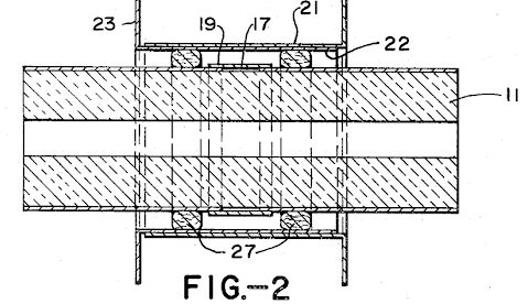
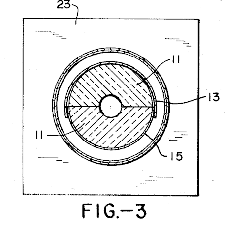
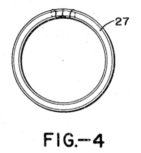
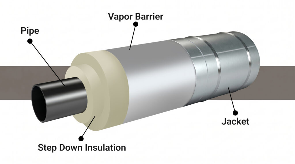
The concept was so fundamentally different from accepted industry practice that it ultimately earned federal patent protection. In 1974, McClellan was granted a U.S. Patent for a “Thermal Shield,” formally documenting the innovation that would become the foundation of Pipe Shields’ technology and establishing the company as the original pioneer of pre-insulated support systems.

As Albert Dizon puts it:

“Nobody had ever done that before.” 

Pipe support fig4

Taking It to Market – One Engineer at a Time

McClellan didn’t wait for the industry to come to him. He built product samples, loaded a trailer behind his SUV, and drove coast to coast, east first, then back through every state, spending months on the road, stopping at engineering firms, project offices, and industrial facilities, and putting the product directly in front of design engineers.

Doors were slammed, and skeptics were plentiful. But some engineers said: Let’s try it. And the results spoke clearly. The product performed. Heat loss at support locations was eliminated. Field installation time dropped dramatically compared to conventional methods. Word began to spread through engineering networks.

Critically, McClellan worked to get the pre-insulated support recognized by ASME, the American Society of Mechanical Engineers, whose codes govern piping system design across industries. With backing from Bechtel and Lawrence Livermore, he secured language in the ASME code stating that for insulated lines, pre-insulated pipe supports may be used. It wasn’t yet a standard. But it was code-approved, and for a design engineer, that was enough to justify specifying it.

The Intel Specification – A Market-Defining Win

The most significant commercial breakthrough came when McClellan convinced the design engineers at what would later become Intel Corporation, then operating under the names of its founders, Gordon Moore and Robert Noyce, to adopt Pipe Shields as the specified support solution across all of their facilities.

“All of Intel’s plants domestically and worldwide, their specs only have Pipe Shields model numbers on them,” Albert says. “If you look at every Intel spec right now, you’d only see Pipe Shields.”

That single specification incorporated the product into Intel’s global facility standards. It became one of the most powerful reference points in the company’s commercial history, proof that the pre-insulated support wasn’t a niche solution. It was enterprise-grade, validated by one of the world’s most demanding facility operators.

From San Jose to Vacaville – and into PT&P

From a small rented shop in San Jose, Pipe Shields grew steadily through the late 1970s and 1980s. As demand expanded into larger pipe sizes, 24, 36, and 48 inches, McClellan sold his remaining racquetball holdings and invested in a dedicated manufacturing facility in Vacaville, California, capable of handling the full scope of what the market required.

The timing of the product’s market growth was not coincidental. The 1970s oil crisis had made energy conservation a primary concern across industrial sectors. McClellan’s product offered a direct, quantifiable answer: less heat loss at every support location, lower fuel consumption at every boiler and steam turbine. Heat was money. Pre-insulated supports stopped the loss.

Following McClellan’s passing in the late 1990s, the business was acquired by Piping Technology & Products in 2004, bringing Pipe Shields into a manufacturing and engineering platform with the resources to serve the global market at scale.

The Standard Bearer, Then and Now

Today, Pipe Shields operates as a division of Piping Technology & Products, continuing to manufacture the pre-insulated pipe supports that William McClellan invented, patented, and brought to market through decades of determined, ground-level work. The product line, organized across the alphabetical series that McClellan himself developed to help engineers specify the right support for every application, remains the reference standard in facilities worldwide.

The pre-insulated pipe support is not a new idea to the market. It is the market, and Pipe Shields created it.

Read More

Choosing the Right Pre-Insulated Pipe Support

May 26, 2026

Pre insulated pipe support00 (1)

Many facility owners and engineers assume pre-insulated pipe supports are only necessary for extreme temperature applications such as cryogenic or high-temperature steam lines. However, even when a pipe’s surface temperature feels “not that hot or cold,” pre-insulated supports can provide significant benefits in safety, efficiency, and long-term reliability. This article will help you understand the various types of pre-insulated pipe supports available, so you can select a solution that provides the necessary protection without over-engineering or overspending.

Why Pre-Insulated Pipe Supports Matter

1. Preventing Thermal Bridging

Moderate-temperature fluids can create temperature differences between pipes and supports. Without insulation, the support acts as a thermal bridge, causing heat loss or condensation, leading to increased energy loss, corrosion under insulation (CUI), and inconsistent system temperatures.

2. Controlling Condensation

When pipes are cooler than ambient air (e.g., in chilled water or HVAC lines), condensation can occur. This results in dripping hazards, mold, and corrosion of structural steel and hangers. Even pipes at 50–60 °F (10–16 °C) can sweat in humid conditions.


Controlling condensation


3. Maintaining Process Stability

For temperature-sensitive processes, small fluctuations impact product quality or efficiency. Pre-insulated supports ensure stable temperature profiles throughout the line.

Design Considerations

Use our Pipe Shields selection guide to pick the right pre-insulated pipe support model number and size.

Some important concepts to understand to help select the right pre-insulated pipe support for your application:

1. Proper Support Selection

  • Pre-Insulated Pipe Shoes: Provide load-bearing insulation while elevating the pipe to prevent moisture accumulation and protect against corrosion.
  • High-Density Inserts: Distribute the load while minimizing insulation compression.
  • Vapor Barriers: Essential for chilled or sub-ambient lines to prevent moisture ingress.

2. Material Choices

  • Polyurethane Foam (PUF): Good for chilled water and moderate cold applications.
  • Calcium Silicate or Mineral Wool: Suitable for moderately hot lines
  • Phenolic Foam or Aerogel: Lightweight options with superior thermal resistance.

3. Operating Environments

  • Chilled Water Systems: Lines running between 33 degrees F and 60 degrees F require a rigorous vapor barrier.
  • Cryogenic and LNG Lines: Systems handling ultra-low temperatures must utilize specialized zero-permeability or dual-layer vapor barriers to stop ice build-up.
  • Dual-Temperature Systems: Pipes that alternate between hot and cold cycles require a vapor barrier to protect the insulation during the cold cycle.
  • High-Humidity Environments: Facilities located in moisture-heavy or coastal climates must protect all sub-ambient pipe supports from high vapor drive.

4. Field Considerations

  • Ensure continuous insulation between the standard pipe insulation and the support points. Ensure that there are no gaps.
  • Use proper cladding or jacketing to prevent water intrusion.
  • Verify the compressive strength of insulation matches the pipe load.

Practical Examples

Selecting the correct pre-insulated support involves matching the support type to the temperature and load requirements of your application.

Don’t let temperature fluctuations undermine the performance of your entire system. Choosing the right pre-insulated pipe supports is a wise investment that pays for itself through energy savings and reduced maintenance costs.


Application Fluid Temp Range Reason for Insulated Supports
Chilled Water HVAC Lines for datacenters, semiconductor fabs, and pharmaceuticals 40–55 °F (4–13 °C) Prevent sweating and corrosion
Mild hot-water process lines for datacenters, Semiconductor fabs, and pharmaceuticals 120–180 °F (49–82 °C) Energy efficiency and personnel safety
Food & Beverage pipelines Ambient to 150 °F Sanitary conditions and temperature control

Key Takeaways

  • “Not that hot or cold” does not mean insulation is unnecessary. Even for moderate temperature variances, pre-insulated can improve piping safety, efficiency and reliability.
  • Pre-insulated pipe supports prevent condensation, energy loss, and corrosion, protecting both your system and personnel.
  • Proper materials, design, and installation are crucial for long-term performance.

Recommended Action. Evaluate every piping system, regardless of temperature, for potential thermal bridging, condensation risk, and process stability issues. Consult insulation and support manufacturers to specify the right product for your application.

Partner with Piping Technology & Products and Pipe Shields for Pre-Insulated Pipe Supports

Every new project brings the challenge of coordinating materials, managing complex engineering challenges, and preparing for unexpected delays. Rapid Response really looks like ingenuity, flexibility, and execution under pressure.

Pipe Shields Inc. pioneered the design and manufacture of pre-insulated pipe supports, slides, guides and anchors and is a subsidiary of Piping Technology and Products, Inc. Our products are ubiquitous, serving diverse industries including hospitals, airports, semiconductor plants, automotive plants, EV battery plants, data centers, pharmaceutical plants, food processing, petrochemical plants, and power and renewable energy plants sometimes used in cold service lines and some dual temp lines between TCUs (temperature control units) and reactor jackets. Engineers often specify Pipe Shields and PT&P products as the foundation for designing various piping systems.

Since last year, our Houston manufacturing facility has produced over 100,000 units of this support, demonstrating our capacity and reliability. We were the first in the industry to employ the use of high-speed manufacturing automation to facilitate the cutting of the high-density calcium silicate to meet tight deliveries required for the projects.  The advent of computer-controlled cutting equipment has significantly improved our manufacturing processes at PT&P. By integrating these advanced technologies, we have achieved substantial enhancements in manufacturing operations, enabling unparalleled accuracy in cutting high-density insulation. Computer-controlled cutting equipment allows for intricate and complex designs that were once challenging or impossible to achieve manually.  Automating cutting processes has not only reduced human error but also enhanced productivity by accelerating production speeds.

Moreover, these systems provide a high level of repeatability, ensuring consistent quality across multiple iterations. This technology has also reduced material waste by approximately 10–15% compared to human cutting, allowing us to remain highly competitive in global pricing.

Read More

Why Data Centers Need Insulated Pipe Jackets

March 18, 2026

Model a4000 insulated pipe support extra heavy bottom jacket w:extended insulation 1In data centers, heat is the enemy. You spend a fortune on sophisticated cooling systems to keep your servers humming, but there is a silent, dripping threat lurking in your mechanical rooms and ceiling voids: uninsulated or poorly insulated piping.

At Pipe Shields, we know that in a facility where 99.999% uptime is the baseline, even a small thermal leak is a massive liability. Here is a look at the specific pain points data center managers face and how our custom insulated pipe jackets provide the ultimate line of defense.

The High Stakes of Data Center Cooling

Data centers rely on chilled water systems to regulate ambient temperatures. When these pipes aren’t properly protected, three major issues emerge:

1. The “Rain” Indoors: Condensation and Moisture

When cold pipes meet the humid air of a mechanical room, condensation forms. In a residential building, a drip is a nuisance; in a data center, it’s a catastrophe.

  • The Pain: Dripping water can lead to short circuits, hardware corrosion, and mold growth.
  • The Value: Pipe Shields jackets are engineered with a vapor-tight seal. By keeping the pipe surface temperature above the dew point, we eliminate sweating entirely, keeping your server racks bone-dry.

2. Thermal Inefficiency

Every BTU of heat gained by your chilled water lines before they reach the CRAH (Computer Room Air Handler) units is wasted money.

  • The Pain: Standard fiberglass wrap often degrades or sags over time, creating “thermal bridges” where cold escapes. Your chillers have to work harder, driving up your PUE (Power Usage Effectiveness) ratio.
  • The Value: Our removable jackets offer great thermal resistance (R−value). They wrap snugly around complex valves, flanges, and elbows: the places where traditional insulation usually fails.

3. Maintenance Downtime

Traditional hard-shell insulation is a nightmare for maintenance. If you need to inspect a valve, the insulation has to be hacked away and replaced (often poorly).

  • The Pain: Maintenance teams often delay inspections because the cleanup is too intensive, leading to undetected leaks or valve failures.
  • The Value: Pipe Shields jackets are removable and reusable. They feature high-quality fastening systems (like Velcro or straps) that let your team peel them back for inspection and cinch them back into place in seconds. No mess, no waste, no specialized tools.

Precision Engineering: The Pipe Shields Difference

We provide insulation and precision thermal integrity. While off-the-shelf solutions leave gaps at critical junctions, Pipe Shields specializes in custom, high-performance thermal envelopes engineered specifically for the high-velocity, high-stakes environment of modern data centers. Our value proposition is built on three pillars:

  • Zero-Gap Engineering: We eliminate the thermal bypass common in standard wraps by custom-tailoring every jacket to your specific valve, flange, and pipe geometry.
  • Operational Agility: Our jackets transform a two-hour maintenance teardown into a two-minute “peel-and-press” operation, keeping your facility agile and your technicians productive.
  • PUE Optimization: By reducing heat gain in chilled water loops, Pipe Shields directly lowers your Power Usage Effectiveness (PUE) ratio, turning insulation from a maintenance expense into a measurable energy asset.

FAQ: Data Center Piping & Thermal Management

What are the risks of uninsulated chilled water pipes in a data center?

The primary risks include condensation (which leads to equipment-damaging drips), increased PUE due to thermal loss, and microbial growth (mold) in damp insulation. Pipe Shields jackets mitigate these by maintaining surface temperatures above the dew point and providing a vapor-tight barrier.

How does removable pipe insulation improve data center PUE?

Removable insulation jackets from Pipe Shields improve Power Usage Effectiveness (PUE) by preventing thermal gain in chilled water loops. When water stays colder on its way to the CRAH units, the chillers cycle less frequently, directly reducing the facility’s total energy consumption.

Are Pipe Shields jackets compliant with data center fire codes?

Yes. Pipe Shields jackets are manufactured using high-temperature, flame-retardant materials that meet or exceed ASTM E84 and UL 723 standards for flame spread and smoke development, which are critical for indoor air quality and safety in mission-critical environments.

Why use removable jackets instead of traditional fiberglass stay-on insulation?

Traditional insulation is often destroyed during routine valve inspections, leading to temporary fixes that become permanent energy leaks. Pipe Shields’ removable jackets are reusable for the life of the system, reducing material waste and ensuring that insulation is actually replaced after every maintenance check.

Can insulated jackets prevent sweating on complex valves and fittings?

Yes. Standard pipe wrap often fails in complex geometries such as butterfly valves or T-joints. Pipe Shields uses 3D patterning to ensure a snug fit for irregular shapes, eliminating air gaps where moisture typically collects and condenses.

Why Pipe Shields?

Not all insulation is created equal. Data centers require materials that meet strict fire safety codes and provide long-term durability.  Our company is the pioneer of pre-insulated pipe supports; we invented and patented the design of these for all ranges and temperatures. We understand the importance of durable insulation.

When it comes to our insulated pipe jackets, they are:

  • Customized: Tailored to your specific piping dimensions for zero gaps.
  • Fire-Rated: Constructed with materials that meet or exceed industry safety standards.
  • Durable: Resistant to the chemicals and wear-and-tear common in industrial cooling loops.

The Bottom Line

Your data center is the backbone of your business. A simple pipe leak or energy drain compromises your infrastructure. Insulated pipe jackets from Pipe Shields are an investment in uptime and safety.

Is it time to fine-tune your data center’s cooling loop? Reach out to our Engineering Team for a consultation or a custom quote for your facility.

Read More

The Maintenance Manager’s Guide to Inspecting Chilled Water Piping

March 3, 2026

Pre-insulated pipe supports from Pipe Shields deliver effective thermal management.If you manage a facility with a chilled water system, you know the sweat is your biggest enemy. That moisture is the first sign that your insulation has failed, and your pipes are likely corroding underneath.
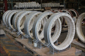
Most of these failures happen at the support points. When a heavy pipe sits in a standard metal hanger, it eventually crushes the insulation. This breaks the vapor barrier, creates a “cold spot,” and starts a cycle of energy loss and rust. The good news? You don’t have to shut down the whole building to fix it.

Stop the Sweat: A 4-Point Inspection Checklist

When you’re walking your lines, don’t just look for leaks. Look for these four red flags that tell you a support has failed:

  1. The “Saggy” Jacket: Look at your hangers. Is the pipe centered in the ring, or is it resting directly on the metal? If the insulation looks pinched or flattened at the bottom, the thermal barrier is gone.
  2. Ice or Water Droplets: If you see condensation or ice forming on the outside of the insulation near a hanger, your vapor barrier is breached.
  3. Discolored Jacketing: Brown or rust-colored staining near a support is a “smoking gun” for Corrosion Under Insulation (CUI). The pipe is literally rusting inside its sleeve.
  4. Loose Hangers: If a hanger has vibrated loose or shifted, it can slice through the vapor barrier jacket like a knife.

The “Hot-Swap” Method: Upgrading to Pre-Insulated Pipe Supports

You don’t need a full system shutdown to fix a crushed support. By using Pipe Shields pre-insulated supports, your team can perform a “hot-swap” during a standard maintenance window. These units combine high-density insulation and a protective metal shield into a single piece, so you replace both the problem and the insulation at once.

How to Swap a Support in 5 Steps

  • Step 1: Brace the Pipe. Use a temporary floor jack or a secondary hanger nearby to take the weight off the support you are replacing.
  • Step 2: Clear the Old Insulation. Cut away the damaged or crushed insulation at the hanger point. Clean the pipe surface to ensure no moisture is trapped.
  • Step 3: Slide the pipe shield into place. Open the clevis hanger and slide the pipe shield unit directly onto the pipe. Our units are designed to fit perfectly into standard hanger sizes.
  • Step 4: Seal the Joints. This is the most important part. Use vapor-barrier tape to seal the ends of the Pipe Shield to the existing pipe insulation. This recreates the airtight seal you need to prevent sweating.
  • Step 5: Tighten and Move On. Once the shield is centered in the hanger, tighten the bolt and remove your temporary brace. You’ve just permanently fixed a weak link in your system.

One Fix, Zero Leaks: The Manager’s Secret to Permanent Pipe Support

Standard field-wrapped insulation at support points almost always fails because it isn’t dense enough to hold the weight of the pipe. Our pre-insulated pipe supports are different. We build the support into the insulation. You get a load-bearing insert that won’t crush, a factory-applied vapor barrier that won’t leak, and a galvanized steel shield that protects the whole assembly. It’s a permanent fix that lowers your energy bills and stops pipe rot in its tracks.

Browse our catalog of pre-insulated supports, or contact a specialist for a quote for your next maintenance window.

FAQ: How to Stop Chilled Water Pipe Sweating and Support Failure

How do I know if I need a pipe shield instead of just more insulation?

If the pipe is heavy enough to compress the insulation material, you need a pipe shield. Standard fiberglass or foam cannot support the weight of a water-filled pipe; it will eventually crush, break the vapor seal, and cause condensation.

Can these be installed while the water is still running?

Yes. Since Pipe Shields are pre-insulated and designed to fit standard hangers, they are ideal for “hot-swapping” during active maintenance without draining the system or shutting down the chillers.

What is the main benefit of a pre-insulated support?

The main benefit is a guaranteed vapor barrier. When you “field-wrap” a hanger, it’s hard to get a perfect seal. Our units are factory-sealed, eliminating the human error that usually leads to CUI and dripping pipes.

Read More

Why Pre-Insulated Pipe Supports Are Essential for Steam Lines

February 26, 2026

Large diameter hot shoes from Pipe ShieldsPlugging the Energy Leak: How Pre-Insulated Pipe Supports Fix Thermal Bridging

In a high-pressure steam environment, heat is your most valuable currency. You invest millions into high-grade boilers and miles of premium insulation to keep that heat where it belongs: inside the pipe. However, many power plants leave a hole in their pocket at every single hanging or resting point. When a bare metal pipe makes direct contact with a metal support, it creates a thermal bridge. This allows heat to bypass your insulation entirely, turning your pipe supports into accidental radiators that bleed energy into the atmosphere 24/7.

Real-world example: 48″ Guided Pre-Insulated Pipe Supports for High Temperatures

The “Heat Sink” Effect and the Science of the Thermal Break

Traditional pipe clamps act as heat sinks, drawing thermal energy away from the steam and through the support structure. This isn’t just an efficiency issue; it’s a reliability nightmare. Localized cooling at support points can lead to condensation and wet steam, which causes internal erosion and water hammer. To stop this, pre-insulated pipe supports use a high-compressive-strength insulating core, such as calcium silicate or heavy-duty polyurethane, to create a thermal break. By nesting the pipe within an insulated insert before the metal clamp ever touches it, you effectively “plug” the bridge, ensuring the insulation envelope remains continuous, and the BTU loss is neutralized.

The “Math of Loss” (in British Thermal Units-BTUs)

Consider a mid-sized power plant with 2,000 support points. If each uninsulated support loses just 150 BTUs per hour (a conservative estimate for high-pressure steam), the plant is hemorrhaging 300,000 BTUs every hour. Over a year of 24/7 operation, that equates to over 2.6 billion BTUs wasted. At current fuel prices, that silent leak is a direct hit to the bottom line that pre-insulated supports could have prevented.

Support Type

Estimated Heat Loss (Btu/hr)

Annual Energy Loss (MMBtu*)

System Impact

Standard “Bare” Metal Clamp 1,200 – 1,800 10.5 – 15.7 High risk of CUI; creates a heat sink.
Field-Wrapped Support 400 – 700 3.5 – 6.1 Inconsistent; prone to insulation crushing.
Pipe Shields Pre-Insulated Support 45 – 85 0.4 – 0.7 95% efficiency gain; maintains vapor barrier.


*Calculated based on 8,760 annual operating hours. MMBtu = 1 Million BTUs.

The Pipe Shields Standard: Engineered to Outlast the Outage

At Pipe Shields, we provide thermal integrity. Our pre-insulated pipe supports are engineered to withstand the extreme temperatures and mechanical loads of the power industry while maintaining a 360-degree vapor barrier. By integrating insulation and support into a single, factory-tested unit, we eliminate human error associated with field-wrapping and ensure your steam system operates at peak thermodynamic efficiency from day one.

Real-world example: 399 Pre-Insulated Pipe Supports for an LNG Facility

FAQ: Solving Your High-Temp Support Challenges

  • What is the best material for pre-insulated steam supports?
    For high-pressure steam, calcium silicate is the gold standard due to its high structural compressive strength and ability to withstand temperatures exceeding 1200°F without degrading.
  • Can’t we just wrap insulation over standard clamps?
    Field-wrapping over clamps is rarely effective. It leaves gaps where the clamp meets the pipe, allows for moisture ingress (CUI), and does not provide the structural thermal break that a pre-insulated insert provides.
  • How do pre-insulated supports impact installation time?
    Pipe Shields’ units are drop-in ready. Because the insulation and shield are pre-assembled, installation is significantly faster than traditional methods, which is critical during tight maintenance outages.
  • Do these supports handle vibration?
    Yes. Our high-density inserts are designed to absorb mechanical vibration and evenly distribute loads, preventing the insulation from crushing or powdering over time.

Plug the BTU Leak: Switch to Pipe Shields. Inefficient supports undermine your plant’s performance. Contact the Pipe Shields engineering team for a custom load calculation and see how our pre-insulated solutions can modernize your steam lines.

Read More
Top