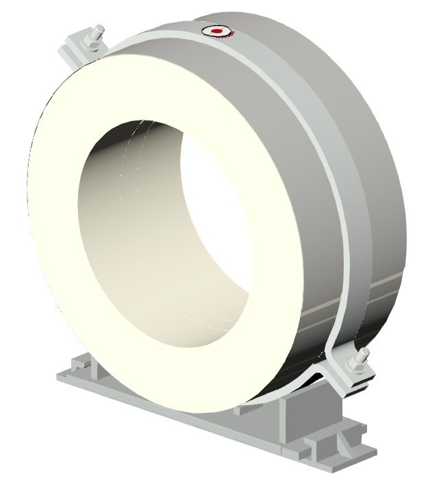

Hardware sold separately. Cross-section & dimension callouts shown in the technical data below.
Laterally Restrained Insulated Pipe Support · Heavy Duty, Base Mounted
B7200
A heavier-duty, laterally restrained, base-mounted, pre-insulated pipe support with slide pads for higher-load applications – accommodating up to 1.5″ of axial movement while providing greater lateral load allowance.
Talk to a pipe support specialist about your application.
1-707-447-5014General Dimensions & Specifications
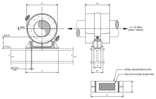
Contact factory for other dimensional, temperature, load, or axial travel requirements. If lateral load is greater than 50% of actual vertical load, contact factory. Available in all insulation thicknesses.
The load ratings represent average values obtained in accordance with accepted test methods and are subject to normal manufacturing variations. Dimensions and ratings are subject to change without notice.
Note: For higher load ratings, see B7300. For greater axial travel, see B8200. For lateral travel, see B5200.
| Pipe Size |
Vert. Load (lbs) |
Insulation Thickness | ||||||||||||||||||||
|---|---|---|---|---|---|---|---|---|---|---|---|---|---|---|---|---|---|---|---|---|---|---|
| 1″ | 1 1/2″ | 2″ | 2 1/2″ | 3″ | 4″ | 5″ | ||||||||||||||||
| B | C | E | B | C | E | B | C | E | B | C | E | B | C | E | B | C | E | B | C | E | ||
| 1/2 | 375 | 4 | 5 | 3.25 | 4 | 5.5 | 4.375 | 4 | 6 | 5.375 | 4 | 7.5 | 7 | 6 | 8 | 8 | 6 | 10 | 10 | 8 | 11.5 | 12.125 |
| 3/4 | 465 | 4 | 5 | 3.25 | 4 | 5.5 | 4.375 | 4 | 6 | 5.375 | 4 | 7.5 | 7 | 6 | 8 | 8 | 6 | 10 | 10 | 8 | 11.5 | 12.25 |
| 1 | 600 | 4 | 5.5 | 4 | 4 | 6 | 5 | 4 | 6.5 | 6.062 | 4 | 7.5 | 7.125 | 6 | 8 | 8.125 | 6 | 10 | 10.125 | 8 | 11.5 | 12.25 |
| 1 1/2 | 870 | 4 | 6 | 4.5 | 4 | 6.5 | 5.5 | 4 | 8 | 7.125 | 4 | 8.5 | 8.125 | 6 | 9.5 | 9.125 | 6 | 11.5 | 11.25 | 8 | 13 | 13.25 |
| 2 | 1005 | 4 | 7 | 5 | 4 | 7.5 | 6.1875 | 4 | 8.5 | 7.125 | 4 | 9 | 8.125 | 6 | 10 | 9.125 | 6 | 12 | 11.25 | 8 | 13.5 | 13.25 |
| 2 1/2 | 1230 | 4 | 7 | 5.5 | 4 | 8.5 | 7.125 | 4 | 9 | 8.125 | 4 | 10 | 9.125 | 6 | 11 | 10.125 | 6 | 12.5 | 12.25 | 8 | 14 | 14.5 |
| 3 | 1425 | 4 | 7.5 | 6.187 | 4 | 8.5 | 7.125 | 4 | 9 | 8.125 | 4 | 10 | 9.125 | 6 | 11 | 10.125 | 6 | 12.5 | 12.375 | 8 | 14 | 14.625 |
| 4 | 2250 | 4 | 9.5 | 7.25 | 4 | 10 | 8.25 | 4 | 11 | 9.25 | 4 | 12 | 10.25 | 6 | 13 | 11.375 | 6 | 14.5 | 13.375 | 8 | 16 | 15.625 |
| 5 | 2820 | 4 | 12.5 | 8.5 | 4 | 13 | 9.5 | 4 | 14.5 | 10.5 | 4 | 16 | 11.625 | 6 | 17 | 12.625 | 6 | 19 | 14.875 | 8 | 20.5 | 16.875 |
| 6 | 3420 | 4 | 12 | 9.5 | 4 | 13.5 | 10.5 | 4 | 15 | 11.625 | 4 | 16 | 12.625 | 6 | 17.5 | 13.625 | 6 | 18.5 | 15.875 | 8 | 20.5 | 17.875 |
| 8 | 4500 | 4 | 16 | 11.625 | 4 | 17 | 12.625 | 4 | 18.5 | 13.625 | 6 | 19 | 14.875 | 6 | 20 | 15.875 | 6 | 21.5 | 18.125 | 8 | 23 | 20.125 |
| 10 | 5400 | 4 | 19 | 13.875 | 4 | 19.5 | 15.125 | 4 | 20.5 | 16.125 | 6 | 21 | 17.125 | 6 | 22 | 18.125 | 6 | 23.5 | 20.125 | 8 | 25.5 | 22.125 |
| 12 | 5850 | 4 | 21 | 16.125 | 4 | 21.5 | 17.125 | 4 | 22.5 | 18.125 | 6 | 23.5 | 19.125 | 6 | 24 | 20.125 | 6 | 26 | 22.125 | 8 | 27.5 | 24.125 |
| 14 | 6750 | 4 | 22 | 17.125 | 4 | 23 | 18.125 | 4 | 24 | 19.125 | 6 | 24.5 | 20.125 | 6 | 25.5 | 21.125 | 6 | 27.5 | 23.125 | 8 | 28.5 | 25.125 |
| 16 | 7800 | 4 | 23.5 | 19.375 | 4 | 24 | 20.375 | 6 | 25 | 21.375 | 6 | 26 | 22.375 | 6 | 27 | 23.375 | 8 | 28 | 25.375 | 8 | 29 | 27.375 |
| 18 | 8550 | 4 | 25.5 | 21.375 | 4 | 26.5 | 22.375 | 6 | 27.5 | 23.375 | 6 | 28 | 24.375 | 6 | 28.5 | 25.375 | 8 | 29.5 | 27.375 | 8 | 31 | 29.375 |
| 20 | 9150 | 4 | 28 | 23.375 | 4 | 28.5 | 24.375 | 6 | 29 | 25.375 | 6 | 29.5 | 26.375 | 6 | 30 | 27.375 | 8 | 31.5 | 29.375 | 8 | 33 | 31.375 |
| 24 | 9600 | 4 | 31 | 27.375 | 4 | 32 | 28.375 | 6 | 32.5 | 29.375 | 6 | 33 | 30.375 | 6 | 34 | 31.375 | 8 | 35.5 | 33.375 | 8 | 37 | 35.375 |
| 30 | 12600 | 4 | 37 | 33.625 | 6 | 38 | 34.625 | 6 | 38.5 | 35.625 | 6 | 39.5 | 36.625 | 6 | 40.5 | 37.625 | 8 | 42 | 39.625 | 8 | 43.5 | 41.625 |
| 36 | 14700 | 4 | 43 | 40.125 | 6 | 43.5 | 41.125 | 6 | 44.5 | 42.125 | 6 | 45.5 | 43.125 | 6 | 46 | 44.125 | 8 | 47.5 | 46.125 | 8 | 49.5 | 48.125 |
| 42 | 16650 | 4 | 49 | 46.125 | 6 | 50 | 47.125 | 6 | 51 | 48.125 | 6 | 51.5 | 49.125 | 6 | 52.5 | 50.125 | 8 | 54 | 52.125 | 8 | 55.5 | 54.125 |
| All dimensions in inches. “B”, “C” and “E” refer to the drawing above. | ||||||||||||||||||||||
Application
Model B7200 is designed for use on:
- Hot water
- Cold water
- Chilled water
- Dual temperature
- Steam
- Air
- Gas
- Vacuum
Intended for installation on:
- Flat surfaces
Temperature Range
Standard: +40°F to +1200°F CalSil Insulation
Note: Up to 1800°F available upon request.
Cryogenic: -275°F to +275°F Urethane Insulation.
Add U after the model number (i.e., B7200U)
Features
- All pipe sizes
- Eliminates welding to pipe
- Insulating structural inserts for load transfer
- Other I.D.’s and/or O.D.’s available on request
- Factory mounted polyethylene slide pad on steel mounting plate
- Easy installation
- Overlapping galvanized sheet metal jacket
- Stainless steel to UHMW polyethylene slide
Material Data
| B7200 Spec Doc | Applicable PSI spec. doc.: No. 209 |
|---|---|
| Insulation | Calcium silicate, asbestos-free, treated with water repellant |
| Jackets | Galvanized steel, ASTM A-653 |
| Glue | Industrial contact adhesive |
| Structural Inserts | High-density calcium silicate, asbestos-free, treated with water repellant |
| Steel Straps / Base | Carbon steel, ASTM A-36 |
| Fasteners | ASTM A-307, plated |
| Slide Pad | UHMW polyethylene (PTFE optional) |
| Coating | Primer coated or hot dipped galvanized. Other coatings available upon request. |
| Cryogenic Insulation | Urethane (for -275°F to +275°F service, model B7200U) |
Need a formal submittal?
Formal submittal sheets are available.
Installation Guide
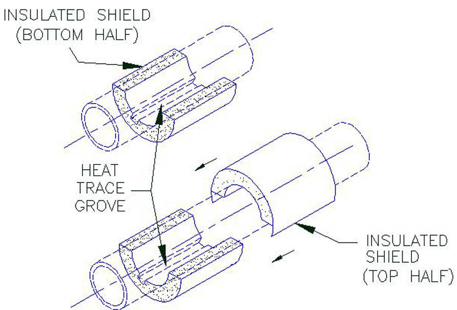
Model A1000 – A4000 & A9000
1. Position the bottom half of the insulated hanger shield (insulating structural material, sheet metal jacket and load plate where applicable) on the pipe at the applicable support location as shown.
2. Hold the top half of the shield firmly. Open the overlapping sheet metal jacket and gently slide into position the top half of the insulated shield over the bottom half shield as shown.
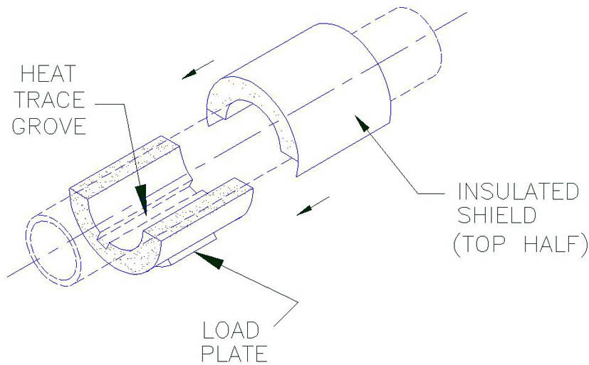
Model A5000 – A8400
1. When used on a flat surface, position shield so that it is centered on the structural steel.
2. When used with a clevis hanger, position shield symmetrically.
3. When models include heat trace groves, the number and location may vary. Check with design drawings for exact number and location. Ensure that the heat tracing cable is properly positioned inside the grove of the shield.
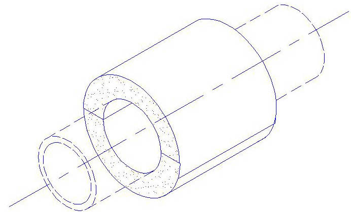
Completed Assembly Without Load Plate
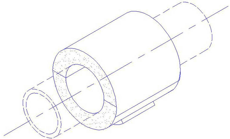
Completed Assembly With Load Plate
Downloads & resources
Custom Design Request
Need other I.D.'s, O.D.'s, temperatures or loads? Submit a custom design request.
Start Request →Revit RFA 3D Model
A1000 Insulated Pipe Support Revit RFA model for BIM & coordination workflows.
Download 3D Model →