
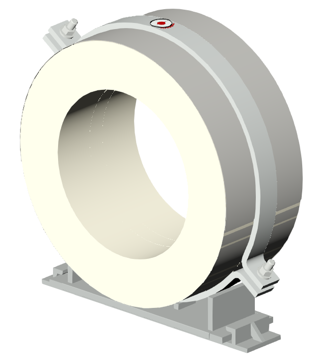
Insulated Pipe Support - Extra Heavy Bottom Jacket w/Extended Insulation - A4000 - Details
Download 3D Models
Custom Design Request
Request a Quote

Pipe Shields Inc. manufactures pre-insulated pipe supports, slides, guides and anchors and is a subsidiary of Piping Technology and Products, Inc.


| Oper. Temp. °F |
Mult. Factor “F” |
|---|---|
| 500 | 0.90 |
| 750 | 0.75 |
| 1000 | 0.50 |
| 1200 | 0.30 |
| TABLE III | |
| Pipe Size |
MAXIMUM LOAD RATING (LBS) |
||
|---|---|---|---|
| On Flat Surface (a) (d) |
On Pipe Roll (b) (d) |
In Ring or Clevis Hanger (c) (d) |
|
| 1/2 | 40 | 35 | 45 |
| 3/4 | 45 | 40 | 50 |
| 1 | 65 | 60 | 70 |
| 1 1/4 | 80 | 70 | 90 |
| 1 1/2 | 110 | 100 | 120 |
| 2 | 140 | 125 | 155 |
| 2 1/2 | 165 | 150 | 220 |
| 3 | 200 | 180 | 275 |
| 3 1/2 | 250 | 225 | 325 |
| 4 | 300 | 270 | 375 |
| 5 | 400 | See A6000 |
475 |
| 6 | 450 | 575 | |
| 8 | 500 | 800 | |
| 10 | 525 | 1100 | |
| 12 | 575 | 1300 | |
| 14 | 600 | 1500 | |
| 16 | 625 | 1700 | |
| 18 | 650 | 1900 | |
| 20 | 700 | 2100 | |
| 24 | 775 | 2400 | |
| TABLE I | |||
Contact factory for other dimensions,
temperatures, and loads.
Available in all insulation thicknesses.
The load ratings represent average values obtained in accordance with accepted
methods and are subject to normal manufacturing variations. Dimensions and ratings
are subject to change without notice.
a) To develop maximum load rating, width of support surface should be at least 1/2 of dimension “A” in Table II.
b) Divide “A” in Table II by 6 to find maximum allowable travel on pipe roll (+/- from centered position).
c) To develop maximum load rating, use band, ring or clevis hanger with manufacturer’s load rating equal to or greater than values shown in Table I.
d) To obtain load ratings for operating temperatures of 500° F and higher, multiply load rating by factor “F” in Table III.
| Iron Pipe Size |
Insulation Thickness | Copper Tubing Size O.D. |
|||||||||||||||||
|---|---|---|---|---|---|---|---|---|---|---|---|---|---|---|---|---|---|---|---|
| 1/2 | 3/4 | 1 | 1 1/2 | 2 | 2 1/2 | 3 | 3 1/2 | 4 | |||||||||||
| A | B | A | B | A | B | A | B | A | B | A | B | A | B | A | B | A | B | ||
| 1/2 – 1 1/2 | 6 | 24 | 6 | 24 | 6 | 24 | 6 | 24 | 6 | 24 | 6 | 24 | 6 | 24 | 6 | 24 | 6 | 24 | 5/8 – 1 5/8 |
| 2 | 6 | 24 | 6 | 24 | 6 | 24 | 6 | 24 | 6 | 24 | 6 | 24 | 6 | 24 | 6 | 24 | 6 | 24 | 2 1/8 |
| 2 1/2 – 4 | 6 | 20 | 6 | 20 | 6 | 20 | 6 | 20 | 6 | 20 | 6 | 20 | 9 | 20 | 9 | 20 | 9 | 20 | 2 5/8 – 4 1/8 |
| 5 | 6 | 20 | 6 | 20 | 6 | 20 | 6 | 20 | 9 | 20 | 9 | 20 | 9 | 20 | 5 1/8 | ||||
| 6 – 7 | 6 | 20</> | 6 | 20 | 6 | 20 | 6 | 20 | 9 | 16 | 9 | 16 | 9 | 16 | 6 1/8 | ||||
| 8 – 10 | 9 | 16 | 9 | 16 | 9 | 16 | 9 | 16 | 9 | 16 | 9 | 16 | 8 1/8 – 10 1/8 | ||||||
| 12 – 18 | 12 | 16 | 12 | 16 | 12 | 16 | 12 | 16 | 12 | 16 | 12 | 16 | 12 1/8 | ||||||
| 20 – 24 | 18 | 16 | 18 | 16 | 18 | 16 | 18 | 16 | 18 | 16 | 18 | 16 | |||||||
| TABLE II “B” = gauge of sheet metal jacket (bottom jacket approx. 2 X ga. of top jacket) |
|||||||||||||||||||
Model A4000 is designed for use on:
Intended for installation on:
Temperature Range:
Standard: +40°F to +1200°F CalSil Insulation
Note: Up to 1800°F available upon request.
Cryogenic: -275°F to +275°F Urethane Insulation.
Add U after the model number (i.e., A4000U)
Performance test results on file:
Available upon request.
Formal submittal sheets available