Resources
Resources
FAQ Category: Engineer Questions
Pipe Shields Installation Videos
General Installation for B-Series

General Installation for C-Series

Pipe Shields to Value Engineered Products, Inc.
| Pipe Shields, Inc. Figure Numbers to Value Engineered Products Figure Numbers Equivalency Chart | |
|---|---|
| The information provided in our equivalency section is a general guide only and should not be treated as a substitute for detailed technical advice in relation to individual circumstances or particular applications of pipe support products. Please contact Pipe Shields, Inc. if you require such advice. PTP/PSI is not responsible for customer selection and/or use of competitor products based on equivalency chart. | |
| Pipe Shields Figure No. | Value Engineered Products Figure No. |
| Pipe Shields A1000 | Pro-Shield |
| Pipe Shields A2000 | Pro-Shield |
| Pipe Shields A3000 | Pro-Shield |
| Pipe Shields A4000 | Pro-Shield |
| Pipe Shields A5000 | MaxSpan R.H. |
| Pipe Shields A6000 | MaxSpan R.H. |
| Pipe Shields A7000 | MaxSpan R.H. |
| Pipe Shields A7200 | MaxSpan R.H. |
| Pipe Shields A7400 | MaxSpan R.H. |
| Pipe Shields A8000 | MaxSpan R.H. |
| Pipe Shields A8200 | MaxSpan R.H. |
| Pipe Shields A8400 | MaxSpan R.H. |
| Pipe Shields A9000 | MaxSpan |
| Pipe Shields B1000 | PS-Series(Axial+/-2") |
| Pipe Shields B1100 | PS-Series(Axial+/-2") |
| Pipe Shields B1200 | PS-Series(Axial+/-2") |
| Pipe Shields B1300 | PS-Series(Axial+/-2") |
| Pipe Shields B2000 | PS-Plus Series(Axial+/-4.5") |
| Pipe Shields B2100 | PS-Plus Series(Axial+/-4.5") |
| Pipe Shields B2200 | PS-Plus Series(Axial+/-4.5") |
| Pipe Shields B2300 | PS-Plus Series(Axial+/-4.5") |
| Pipe Shields B3000 | PG-Series(Axial+/-2") |
| Pipe Shields B3100 | PG-Series(Axial+/-2") |
| Pipe Shields B3200 | PG-Series(Axial+/-2") |
| Pipe Shields B3300 | PG-Series(Axial+/-2") |
| Pipe Shields B4000 | PS-Plus Series(Axial+/-4.5") |
| Pipe Shields B4100 | PS-Plus Series(Axial+/-4.5") |
| Pipe Shields B4200 | PS-Plus Series(Axial+/-4.5") |
| Pipe Shields B4300 | PS-Plus Series(Axial+/-4.5") |
| Pipe Shields B5000 | No Equal |
| Pipe Shields B5100 | No Equal |
| Pipe Shields B5200 | No Equal |
| Pipe Shields B5300 | No Equal |
| Pipe Shields B6000 | No Equal |
| Pipe Shields B6100 | No Equal |
| Pipe Shields B6200 | No Equal |
| Pipe Shields B6300 | No Equal |
| Pipe Shields B7000 | No Equal |
| Pipe Shields B7100 | No Equal |
| Pipe Shields B7200 | No Equal |
| Pipe Shields B7300 | No Equal |
| Pipe Shields B8000 | No Equal |
| Pipe Shields B8100 | No Equal |
| Pipe Shields B8200 | No Equal |
| Pipe Shields B8300 | No Equal |
| Pipe Shields C1000 | No Equal |
| Pipe Shields C1100 | No Equal |
| Pipe Shields C2000 | No Equal |
| Pipe Shields C2100 | No Equal |
| Pipe Shields C3000 | No Equal |
| Pipe Shields C3100 | No Equal |
| Pipe Shields C3200 | No Equal |
| Pipe Shields C3300 | No Equal |
| Pipe Shields C4000 | No Equal |
| Pipe Shields C4100 | No Equal |
| Pipe Shields C4200 | No Equal |
| Pipe Shields C4300 | No Equal |
| Pipe Shields D1000 | No Equal |
| Pipe Shields D2000 | No Equal |
| Pipe Shields D3000 | No Equal |
| Pipe Shields D3100 | No Equal |
| Pipe Shields D3200 | No Equal |
| Pipe Shields D3300 | No Equal |
| Pipe Shields D4000 | No Equal |
| Pipe Shields D5000 | No Equal |
| Pipe Shields D6000 | No Equal |
| Pipe Shields D6100 | No Equal |
| Pipe Shields D6200 | No Equal |
| Pipe Shields D6300 | No Equal |
| Pipe Shields E1000 | No Equal |
| Pipe Shields E1100 | No Equal |
| Pipe Shields E1200 | No Equal |
| Pipe Shields E1300 | No Equal |
| Pipe Shields E2000 | No Equal |
| Pipe Shields E2100 | No Equal |
| Pipe Shields E2200 | No Equal |
| Pipe Shields E2300 | No Equal |
| Pipe Shields G1000 | No Equal |
| Pipe Shields G1200 | No Equal |
| Pipe Shields G2000 | No Equal |
| Pipe Shields G2200 | No Equal |
| Pipe Shields G3000 | No Equal |
| Value Engineered Products Figure Numbers to Pipe Shields Figure Numbers Equivalent | |
| Value Engineered Products Figure No. | Pipe Shields Figure No. |
| Pro-Shield | Pipe Shields A1000 |
| Pro-Shield | Pipe Shields A2000 |
| Pro-Shield | Pipe Shields A3000 |
| Pro-Shield | Pipe Shields A4000 |
| MaxSpan R.H. | Pipe Shields A5000 |
| MaxSpan R.H. | Pipe Shields A6000 |
| MaxSpan R.H. | Pipe Shields A7000 |
| MaxSpan R.H. | Pipe Shields A7200 |
| MaxSpan R.H. | Pipe Shields A7400 |
| MaxSpan R.H. | Pipe Shields A8000 |
| MaxSpan R.H. | Pipe Shields A8200 |
| MaxSpan R.H. | Pipe Shields A8400 |
| MaxSpan | Pipe Shields A9000 |
| PS-Series(Axial+/-2") | Pipe Shields B1000 |
| PS-Series(Axial+/-2") | Pipe Shields B1100 |
| PS-Series(Axial+/-2") | Pipe Shields B1200 |
| PS-Series(Axial+/-2") | Pipe Shields B1300 |
| PS-Plus Series(Axial+/-4.5") | Pipe Shields B2000 |
| PS-Plus Series(Axial+/-4.5") | Pipe Shields B2100 |
| PS-Plus Series(Axial+/-4.5") | Pipe Shields B2200 |
| PS-Plus Series(Axial+/-4.5") | Pipe Shields B2300 |
| PG-Series(Axial+/-2") | Pipe Shields B3000 |
| PG-Series(Axial+/-2") | Pipe Shields B3100 |
| PG-Series(Axial+/-2") | Pipe Shields B3200 |
| PG-Series(Axial+/-2") | Pipe Shields B3300 |
| PS-Plus Series(Axial+/-4.5") | Pipe Shields B4000 |
| PS-Plus Series(Axial+/-4.5") | Pipe Shields B4100 |
| PS-Plus Series(Axial+/-4.5") | Pipe Shields B4200 |
| PS-Plus Series(Axial+/-4.5") | Pipe Shields B4300 |
Pipe Shields to Clement
Pipe Shields to Bergen/Carpenter & Paterson
Pipe Shields to National Pipe Hanger
Cryoshoes Support Specifications
Scope
This specification covers the requirements for the design, fabrication and use of our pre-insulated low temperature pipe supports. These supports are for pipes having surface temperature ranges of –460 ˚F (-273 ˚C ) to 280 ˚F (138 ˚C ).
General Requirements
- Cryogenic pipe supports shall comply with the following standards:
- ANSI/ASME B31.1 & B31.3
- Manufacturers Standardization Society SP-58, 69, & 89.
- The following criteria shall be considered in the selection of low temperature pre-insulated pipe supports:
- Vertical, lateral and axial support design load limits.
- Vertical, lateral, and axial support design travel limits.
- Temperature of the cryogenic pipe support, at the pipe surface, and ambient conditions.
- All test or pre-operational loads that may exceed normal operating conditions.
- Any dimensional clearances needed during installation and operation should be specified.
- Material for any items that will be welded directly to the pipe.
- All loading and displacements caused by seismic, hydraulic surge, or other disturbances.
- Temperature at the support steel.
- Upon request by the purchaser or the end user, design calculations of supports will be made available for review.
- Upon request by the purchaser or the end user, localized stress calculations for lugs and other welded attachments will be made available for review.
- Prior to placing an order, all special requirements such as mill test reports, material certification or non-standard materials must be specified.
Design Criteria
- The load bearing insulating materials used in the pre-insulated pipe support shall be the same material that was used to rate the support.
- At the request of the end user or the purchaser, we will make available compressive strength and thermal conductivity testing results of the high density polyurethane in the format provided by MSS SP-89. Testing will be done at the maximum temperature of -196°C .
- A description of the quantity of load that can be applied to the support shall be provided for evaluation upon request. A minimum safety factor of 5 at the system design temperature shall be used to determine the maximum load.
- Testing for compressive strength properties shall comply with ASTM D1621, the standard testing method, for compressive properties of Rigid Cellular Plastics.
- Testing for thermal conductivity shall comply with ASTM C177, Steady State Heat Flux Measurements and Thermal Transmission Properties, by means of the Guarded Hot Plate Apparatus.
- Load bearing element capacity shall be demonstrated at the system design temperature and load.
- The pre-insulated pipe support assembly shall exert enough clamping force to assure that the support will move axially with the pipe and will not slip when under design conditions.
- All slide plate surfaces shall be designed so that the coefficient of friction will be limited to .1 for the design life without requiring lubrication. Any friction reducing material that requires bonding shall be bonded to a backing structure prior to shipment.
- High density polyurethane shall have the following maximum thermal conductivity:
- 10 lb./cu.in. foam – .114 BTU-in/hr-ft2 – oF (.0164 W/m- o K)
- 14 lb./cu.in. foam – .12 BTU-in/hr-ft2 – oF (.0173 W/m- o K)
- 20 lb./cu.in. foam – .22 BTU-in/hr-ft2 – oF (.0320 W/m- o K)
- CFC’s shall not be used in the manufacture of high-density polyurethane foam.
Fabrication
- All polyurethane foam shall be monolithic and molded oversized so that excess material shall be removed by cutting to achieve the final finished dimensions, the outer skin shall be removed.
- The pre-insulated pipe support shall:
- Come pre-assembled with sufficient insulation extending past the outer metal jacket, allowing the pipe insulator to butt the line insulation against it.
- All exposed surfaces will be coated with mastic to protect the foam from moisture and UV degradation. The mastic will have a minimum perm rating of .02 (ASTM E-96).
- The vapor barrier between the metallic jacket and the insulating material will also have a perm rating of .02.
- The ID and OD dimensions of the insulation shall conform to ASTM specification C585 unless otherwise specified.
- Designs having sliding surfaces shall incorporate two slide plates at each surface. Each slide plate will be made of 3/32″ thick glass filled reinforced PTFE, 25% glass filled, bonded to a 10GA carbon steel backing plate. The PTFE, 25% glass filled, will be recessed ¼” from the edge of the plate.
- All welding shall comply with B31.3 and B31.1 Piping Code and AWS D1.1
- The following items unless otherwise noted on contract drawings shall be in accordance with the following:
- Structure shapes and plate: ASTM A-36
- Bolts and studs: ASTM A-307
- Nuts: A563
Hot Pipe Shoe Support Specifications
Scope
This specification covers the requirements for the design, fabrication and use of our pre-insulated low temperature pipe supports. These supports are for pipes having surface temperature ranges of 40°F (4.4°C) to 1800°F (982°C).
General Requirements
- All insulated pipes shall be supported with pre-insulated pipe supports.
- Pre-Insulated pipe supports shall comply with the following standards:
- ANSI/ASME B31.1 & B31.3
- Manufacturers Standardization Society SP-58, 69, & 89.
- The following criteria shall be considered in the selection of high temperature pre-insulated pipe supports:
- Vertical, lateral and axial support design load limits.
- Vertical, lateral, and axial support design travel limits.
- Temperature of the support, at the pipe surface, and ambient conditions.
- All test or pre-operational loads that may exceed normal operating conditions.
- Any dimensional clearances needed during installation and operation should be specified.
- Material for any items that will be welded directly to the pipe.
- All loading and displacements caused by seismic, hydraulic surge, or other disturbances.
- Temperature at the support steel.
- Upon request by the purchaser or the end user, design calculations of supports will be made available for review.
- Upon request by the purchaser or the end user, localized stress calculations for lugs and other welded attachments will be made available for review.
- Prior to placing an order, all special requirements such as mill test reports, material certification or non-standard materials must be specified.
Design Criteria
- The load bearing insulating materials used in the pre-insulated pipe support shall be the same material that was used to rate the support.
- At the request of the end user or the purchaser, we will make available compressive strength and thermal conductivity testing results of the high density Calcium Silicate insulationin the format provided by MSS SP-89. Testing will be done at the maximum temperature of 1200.
- A description of the magnitude of load that can be applied to the support shall be provided for evaluation upon request. A minimum safety factor of 3 at the system design temperature shall be used to determine the maximum load.
- Testing for compressive strength properties shall comply with ASTM D1621, the standard testing method, for compressive properties of Rigid Cellular Insulation.
- Testing for thermal conductivity shall comply with ASTM C165, Standard Test Method of Measuring Compressive Properties for Thermal Insulation.
- Load bearing element capacity shall be demonstrated at the system design temperature and load.
- The pre-insulated pipe support assembly shall exert enough clamping force to assure that the support will move axially with the pipe and will not slip when under design conditions.
- All slide plate surfaces shall be designed so that the coefficient of friction will be limited to .1 for the design life without requiring lubrication. Any friction reducing material that requires bonding shall be bonded to a backing structure prior to shipment.
- The lower design temperature of the unit at the pipe surface shall be 40°F (4.4°C). The maximum outside design temperature should be 140°F (60°C), the maximum pipe surface temperature should be 1800°F (982°C). For higher or lower temperatures, please contact us.
- The required properties of the load bearing insulating materials under design conditions are:
- The maximum thermal conductivity is 0.77 BTU-in/hr-ft2 – °F at a mean insulation temperature of 700°F.
- There can be a maximum of 1/32″ of non-permanent deformation under the pipe due to permanent consolidation of the load bearing insulation.
- There can be an additional 1/32″ of non-permanent deformation under the pipe.
- The outside surface temperature of the unit shall not exceed 120°F when ambient air is 140°F at all ambient temperatures.
Fabrication
- The pre-insulated pipe support shall:
- Come pre-assembled with sufficient insulation flushed to the outer metal jacket, allowing the pipe insulator to butt the line insulation against it.
- Will withstand the clamping forces transferred by the cradle.
- Will be treated to prevent moisture degradation in accordance with ASTM C656 Type I.
- The ID and OD dimensions of the insulation shall conform to ASTM specification C585 unless otherwise specified.
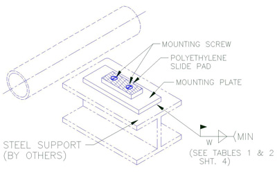
- Designs having sliding surfaces shall incorporate a stainless steel sheet metal sliding surface on the underside of the support base, over a factory mounted and mechanically attached polyethylene slide pad on a carbon steel mounting plate which is welded or bolted to the support steel. Teflon slide padsare optional and may be used to replace the polyethylene pads.
- All welding shall comply with B31.3 and B31.1 Piping Code and AWS D1.1
- The following items unless otherwise noted on contract drawings shall be in accordance with the following:
- Structure shapes and plate: ASTM A-36
- Bolts and studs: ASTM A-307
- Nuts: A563
Foamglas
Foamglas® Technical Information
Foamglas® insulation is a lightweight, rigid insulation composed of millions of completely sealed glass cells. Each cell serves as an insulating agent. Foamglas® is widely used in the cryogenic and hot line pipe supports and is fabricated in various ranges of shapes, thicknesses and sizes to meet the particular requirements of an application.
One unique advantage that Foamglas® has is its very low moisture absorption. Since, Foamglas® insulation is full of closed glass cells, it resists moisture in both liquid and vapor form. This guarantees the long term performance of the insulation. Foamglas® insulation’s resistance to moisture ensures that, properly installed, it retains its original thermal efficiency.
The major advantages and applications of Foamglas® insulation are listed below. For details about the physical and mechanical properties of the Foamglas® material, please refer to the table.
Major Advantages:
• Constant Insulating Efficiency
• Fire Protection
• Corrosion Resistance
• Long Term Dimensional Stability
• Physical Strength
Major Applications:
• Cryogenic and Hot Line Pipe Supports
• Cryogenic Tanks and Vessels
• Chilled and Hot Water Service Lines
• Overfit and Revitalize the Old Insulation
• Composite Insulation Systems for Special Conditions
| Density | Foam Glass(8 pcf) |
| Compressive Strength | 400.00 |
| Flexural Strength (flat wise with grain) (psi) | 80.00 |
| Tensile Strength (with grain)(psi) | N/A |
| Modules of Elasticity (psi) | 1.3 10^6 |
| Closed Cell Content (%) | N/A |
| Temperature (F)-Continuous Operation | 500 max. |
| K-Factor | N/A |
| Thermal Conductivity (btu/hr m^2 of) |
0.7000 |
| Shear (flat wise) (1/8″ thk.) (psi) | N/A |
| Density (lb/in^3) | 0.0046 |
| Water Absorption (%) | 0.070 |
Laminated Beechwood
Permali®/Insulam®/Laminated Beechwood Technical Information
Laminated Beechwood Technical Information Permali® or Insulam® is an insulating material used in applications which require high tensile and compressive strength (see table below). In addition, due to its exceptional resistance to moisture, it serves as a suitable insulator where the support (flare lines & dummy legs) is exposed to harsh environment elements. Permali® or Insulam® is a phenolic laminated (densified, impregnated wood) product made from carefully selected thin beechwood veneers. These wood layers are impregnated under vacuum conditions with a special synthetic resin and then densified through the application of heat and pressure. The result is a homogenous material that combines the great strength and toughness of wood fibers with the excellent stability and dielectric properties of the most advanced thermosetting. The phenolic laminated block material is furnished with cross-directional fibers as shown in Figure 10 below.

| NOTE: Cross laminated. For components in compression or for parts stressed in more than one direction. Sizes to suit most applications. |
| Density | Permali |
| Compressive Strength | 30,000.00 |
| Flectual Strength (flatwise with grain) (psi) |
15,000.00 |
| Tensile Strength (with grain)(psi) |
15,000.00 |
| Modulus of Elasticity (psi) |
2.0 x 10^6 |
| Closed Cell Content (%) | N/A |
| Temperature(F)-Continuous Operation | 221.00 |
| K-Factor | N/A |
| Thermal Conductivity (btu/hr m^2 of) |
0.0018 |
| Shear (flatwise) (1/8″ thick) (psi) |
7200.00 |
| Density (lb/in^3) |
0.0469 |
| Water Absorption (%) | 0.75 |
Polyurethane
Polyurethane Technical Information
Polyurethane foam is one of the major components of pre-insulated pipe supports manufactured at Piping Technology & Products. Polyurethane is different from most plastic materials in that it can be tailored to meet various load requirements of varying applications. Polyurethane foams are produced by reacting an equal ratio of di- or polyisocyanurates with polyols, in the presence of water, which acts as the blowing agent. Polyisocyanurates are formed when a higher ratio of di- or polyisocyanate are mixed with the polyol. All rigid foams made from polyisocyanrate systems have some form of polyurethane in them and can be called polyurethane foam. The physical properties differ very little at high densities. Polyisocyanurate foams are used in applications where dimensional stability over 200 deg F is required. However, for cryogenic applications, where your pipeline insulation is not exposed to high temperatures, PUF is an acceptable substitution.
|
A common method used to obtain a change in load capacity is a change in density. At Piping Technology and Products, we offer 10 lbs. / ft3, 14 lbs. / ft3, and 20 lbs. / ft3 densities. Density varies when the amount of blowing agent (water content) changes. The density of polyurethane decreases with increase in water content (See Fig. 1). This relationship can be shown as follows: W = 3.706 / D1.126 Where: W = % of water content In addition to density, the strength of a rigid urethane foam is also influenced by many factors such as catalyst, surfactant, type of mixing, the type of foaming system: base polyol and isosyanate, and the influence of each of these on the foam cell structure. |
 |
||||||||||||||||||||||||||||||||||||||||||||||||
 Polyurethane is a thermosetting material; however, it does soften slightly with increased temperature and hardens somewhat at very low temperatures. Softening at high temperatures affects the polyurethane in two ways: (a) loss of strength properties and (b) change in foam dimensions (particularly low-density foams). Low temperatures generally have very little effect on polyurethane properties other than to make them a little harder and more brittle. See Fig. 4 for these effects.
|
Polyurethane is anisotropic, or polyurethane is stronger in the direction of foam rise. At Piping Technology and Products, the anisotropic character or directional properties of our polyurethane is reduced by overloading the mold used to form the polyurethane. By overloading the mold, we can control the cell structure and provide uniform physical properties. A relationship between compressive strength and the density of the foam is given in Fig. 3. |
||||||||||||||||||||||||||||||||||||||||||||||||
 |
|||||||||||||||||||||||||||||||||||||||||||||||||
 The relationships of foam’s density with its Elastic Modules in Compression, Tensile Strength, Elastic Modules in Tension, and Shear Strength are given in Figs. 6 through 9 respectively. Please see the following for the respective curves. Piping Technology & Products has a complete manufacturing facility for production of polyurethane required for pipe supports. We invite our customers to visit our facility and observe the fabrication of insulated pipe supports of all types.
|
Rigid polyurethane foams have a relatively large amount of cross-linking as the foam expands. Our suppliers of the raw chemicals control the degree of cross-linking by functionality (higher functionality produces more cross-links) and molecular weight of the components in the blend. The rigid cells provide the poured foam with strength and the interior space provides low thermal conductivity. Water is used as the blowing agent for foam in this 10 to 40 lb. density range.
The relationship between temperature, thermal conductivity and the density of polyurethane foam is shown in Fig. 5. |
||||||||||||||||||||||||||||||||||||||||||||||||
 |
|||||||||||||||||||||||||||||||||||||||||||||||||
|
|||||||||||||||||||||||||||||||||||||||||||||||||
 |
 |
||||||||||||||||||||||||||||||||||||||||||||||||
 |
 |
||||||||||||||||||||||||||||||||||||||||||||||||
Calcium Silicate
Calcium Silicate Technical Information
Calcium Silicate often serves as the insulation for pipe supports in high temperature applications. Calcium Silicate is also known as Thermo-12/Blue. It is an insulating material composed of hydrous calcium silicate which, because of its light weight, low thermal conductivity and exceptional structural strength is ideal for the insulation of high temperature piping and equipment. Sometimes it is also used as block insulation. The pipe insulation comes in a complete selection of sizes. Block styles are available for application to various flat and curved surface areas.
Some of Calcium Silicate’s major advantages and applications are given below:
Major Advantages:
- Temperature Range to 1200°F
- Exceptional Strength
- Low Thermal Conductivity
- Easy Application: available sizes and shapes reduce the number of required joints and make Calcium Silicate easy to work with.
- Energy Savings: low thermal conductivity provides significant energy savings.
- Adaptable: Calcium Silicate can also be used on a various shapes and sizes of surfaces.
- Fire Resistant.
- Low Chloride Content: low corrosivity.
- Asbestos-Free.
Major Applications:
- Hot Line Pipe Supports in Power Generation and Process Industries.
- Indoor and Outdoor Piping and Equipment.
- Block Insulation – insulation of various flat and curved surface areas.
Materials and Temperatures
Insulated Supports: Temperature, Dimensional, and Material Variances
Temperature Ranges
Pipe Shields Inc. strongly recommends the following temperature ranges for our standard insulation material:
| Material | Temperature |
| Calcium Silicate | + 40°F to + 1200°F |
| Polyurethane | – 275°F to + 275°F |
| Permali®/Insulam® | – 328°F to + 248°F |
| Foamglas® | – 450°F to + 900°F |
Material Variances
Our standard paint finish is SP150 Red Oxide Primer which meets full EPA and California safety regulations. Other paint finishes are available upon request:
- Hot dipped galvanized
- In-organic zinc (CZ11HS)
- SP145 grey oxide
- Carbothane 134HG
- Carbozinc 859
Slide plate material and other field welded material are coated with deoxaluminate (silver coating).
Model Designation for Alternate Insulation Materials
| Polyurethane – Add U after Catalog Model Number | Example: Pipe Shields B1000U |
| Urethane/Foamglas® – Add UF after Catalog Model Number | Example: Pipe Shields B1000UF |
| Calcium Silicate/Foamglas® – Add CF after Catalog Model Number | Example: Pipe Shields B1000CF |
Typical Minimum Insulation Thickness
| Temperature Range °F | Pipe Size – Inches | |||||||||||||||
| 2 & Less | 2½ & 3 | 4 | 5 | 6 | 8 | 10 | 12 | 14-16 | 18-20 | 22-24 | 26-30 | 30-38 | 40 & Over | Equipment | ||
| For Thermal Efficiency | ||||||||||||||||
| 1000-1099 | 4½ | 4½ | 5 | 5 | 5½ | 5½ | 6 | 6 | 6½ | 6½ | 6½ | 7 | 7 | 7½ | 7½ | |
| 900-999 | 4½ | 4½ | 4½ | 5 | 5 | 5½ | 5½ | 6 | 6 | 6 | 6½ | 6½ | 7 | 7 | 7 | |
| 800-899 | 4 | 4½ | 4½ | 4½ | 5 | 5 | 5 | 5½ | 5½ | 5½ | 5½ | 6 | 6 | 6½ | 6½ | |
| 700-799 | 3½ | 4 | 4 | 4 | 4½ | 4½ | 4½ | 4½ | 5 | 5 | 5 | 5½ | 5½ | 5½ | 5½ | |
| 600-699 | 3½ | 3½ | 4 | 4 | 4 | 4½ | 4½ | 4½ | 4½ | 4½ | 5 | 5 | 5 | 5 | 5 | |
| 500-599 | 3 | 3 | 3½ | 3½ | 4 | 4 | 4 | 4½ | 4½ | 4½ | 4½ | 4½ | 5 | 5 | 5 | |
| 400-499 | 2½ | 3 | 3 | 3 | 3½ | 4 | 4 | 4 | 4½ | 4½ | 4½ | 4½ | 4½ | 4½ | 4½ | |
| 300-399 | 1½ | 1½ | 2 | 2 | 2 | 2½ | 2½ | 2½ | 3 | 3 | 3½ | 3½ | 4 | 4 | 4 | |
| 200-299 | 1 | 1 | 1½ | 1½ | 1½ | 1½ | 2 | 2 | 2 | 2 | 2 | 2½ | 2½ | 2½ | 2½ | |
| 100-199 | 1 | 1 | 1 | 1 | 1 | 1½ | 1½ | 1½ | 1½ | 1½ | 1½ | 1½ | 1½ | 1½ | 1½ | |
Insulated Pipe Supports


Table 6 – Steam, Gas, or Air Service w/ pipe supported from below (on pipe roll)
|
||||||||||||||||||||||||||||||||||||||||||||||||||||||||||||||||||||


TABLE 5: Water service w/ Pipe supported from below (on pipe roll)
|
||||||||||||||||||||||||||||||||||||||||||||||||||||||||||||||||||||
TABLE 4: Steam, Gas, or Air service w/ Pipe supported from above (in clevis or 2-bolt hanger)
|
||||||||||||||||||||||||||||||||||||||||||||||||||||||||||||||||||||||||||||||||||||||||||||||||||


TABLE 3: Water service w/ Pipe supported from above (in clevis or 2-bolt hanger)
|
||||||||||||||||||||||||||||||||||||||||||||||||||||||||||||||||||||||||||||||||||||||||||||||||||
Steam, Gas, or Air Service, Pipe supported from below (on a flat surface) – Table 2
|
||||||||||||||||||||||||||||||||||||||||||||||||||||||||||||||||||||||||||||||||||||||||||||||||||||||||||||||||||||||||||||||||||||||||||||||||||||||||||||||


TABLE 1: Water Service, Pipe Supported from below (on a flat surface)
|
||||||||||||||||||||||||||||||||||||||||||||||||||||||||||||||||||||||||||||||||||||||||||||||||||||||||||||||||||||||||||||||||||||||||||||||
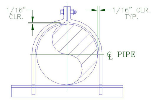
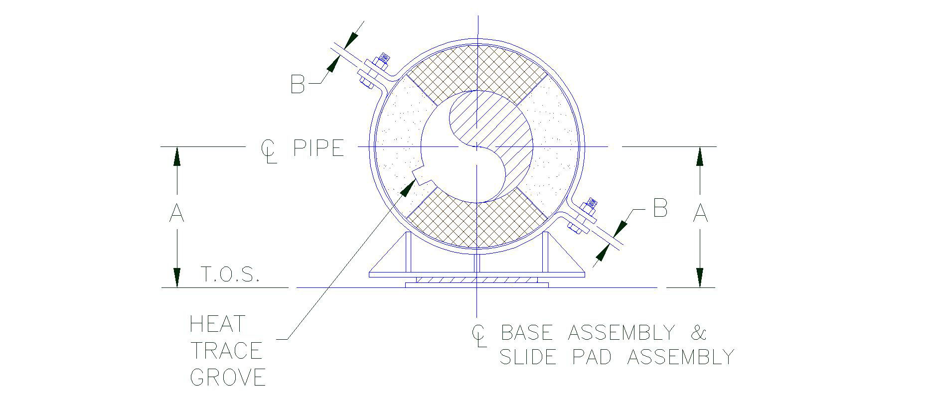
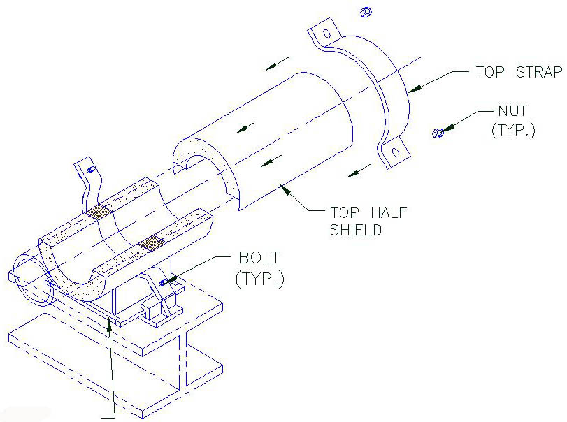
G3000 Series Installation Instructions
Installation Steps

Model G3000 Installation Instructions
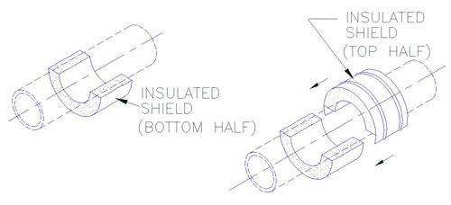
1. A) Position the bottom half of the insulated shield (insulating structural material, sheet metal jacket and load plate) on the pipe at the applicable support location as shown.
2. A) Hold firmly the top half of the shield, open the overlapping sheet metal jacket and gently slide into position the top half of the insulated shield over the bottom half-shield as shown.

3. A) Position the U-Bolt at the appropriate location as shown.
B) Install the nuts and hand tighten until snug tight.
Note:
Provide 1/16″ radial clearance all around between the shield and the U-Bolt except at the bottom as shown in Figure 1.
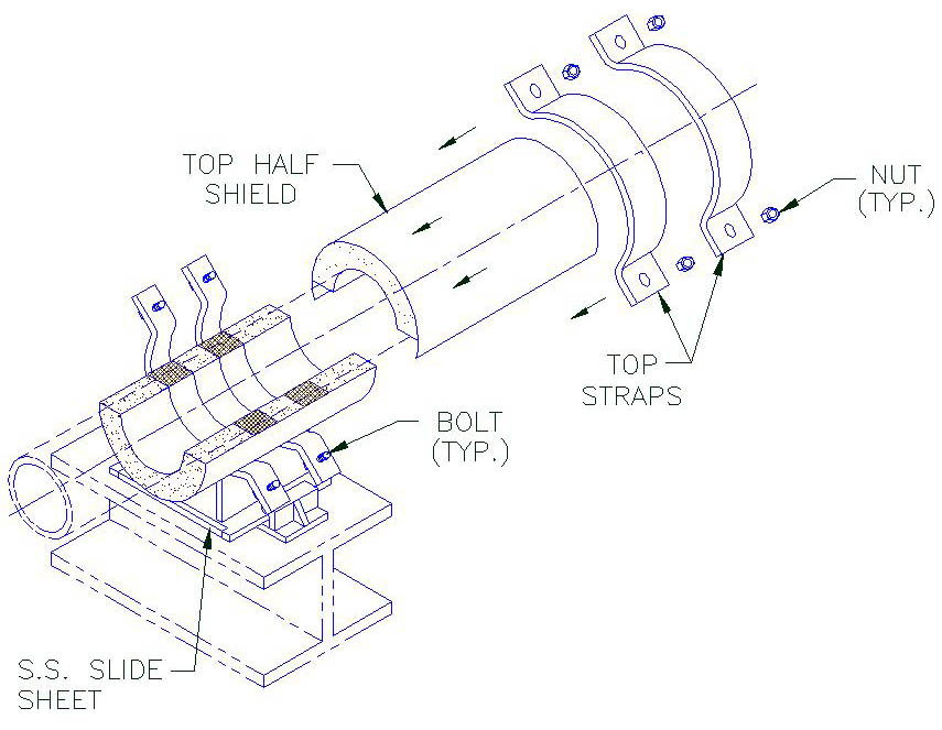
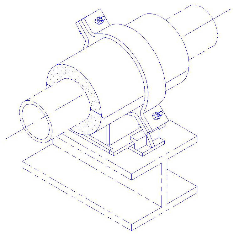
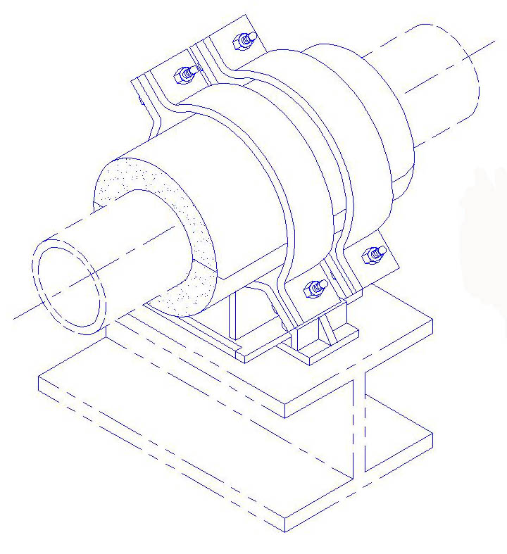
G1000 through G2000 Series Installation Instructions
Installation Steps
Model G1000 Installation Instructions

1. A) Position the guide straps at the applicable support location as shown.
2. A) Install the bolt through the top ears of the straps and hand tighten nut until snug tight.
Model G2000 Installation Instructions

1. A) Position the guide straps at the applicable support location as shown.
2. A) Install the bolts, nut and spring nut as shown. Hand tighten nut and bolt until snug tight.
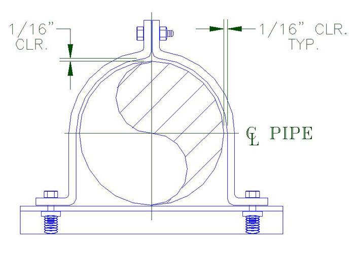
3. A) Install the bolts through the top ears of the straps and hand tighten nuts.B) Install the bolts through the top ears of the straps and the spring nuts and hand tighten until snug tight.
Note:
Provide 1/16″ radial clearance all around between the shield and the strap except at the bottom as shown in Figure 1 and Figure 2.
E2000 through E2300 Pre-Insulated Riser Clamp Installation Instructions
Installation Steps
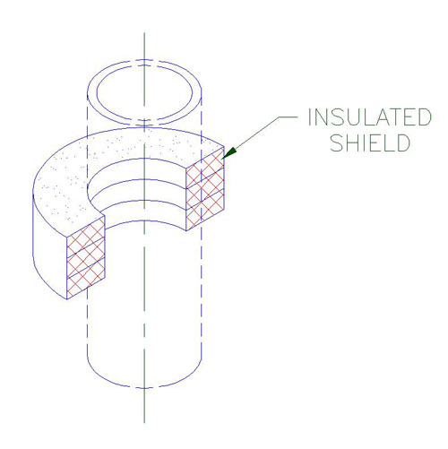
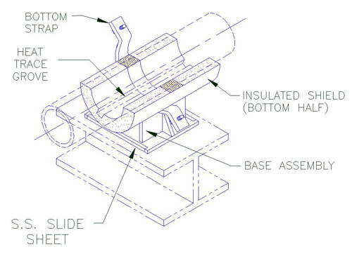
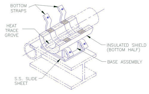
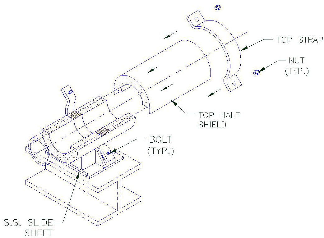
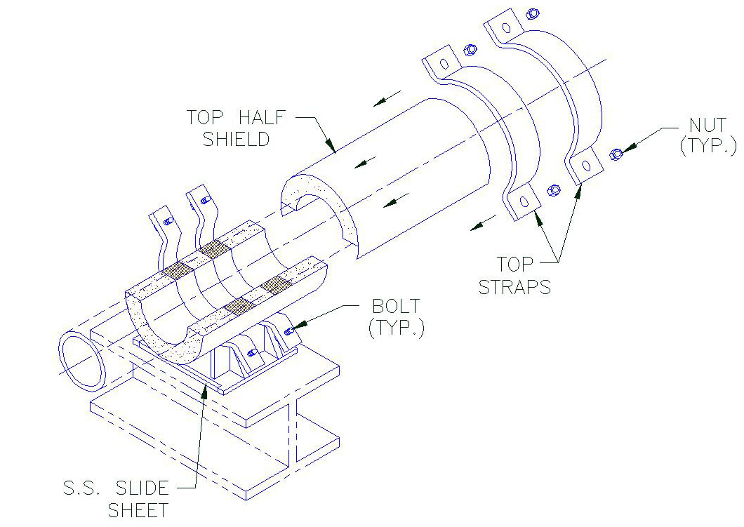
1. A) Position one half of the insulated shield (insulating structural material and sheet metal jacket) on the pipe at the desired location as shown.
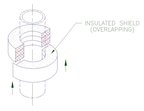
2. A) Gently slide the other half of the insulated shield with the overlapping jacket into position over the previously located half shield.
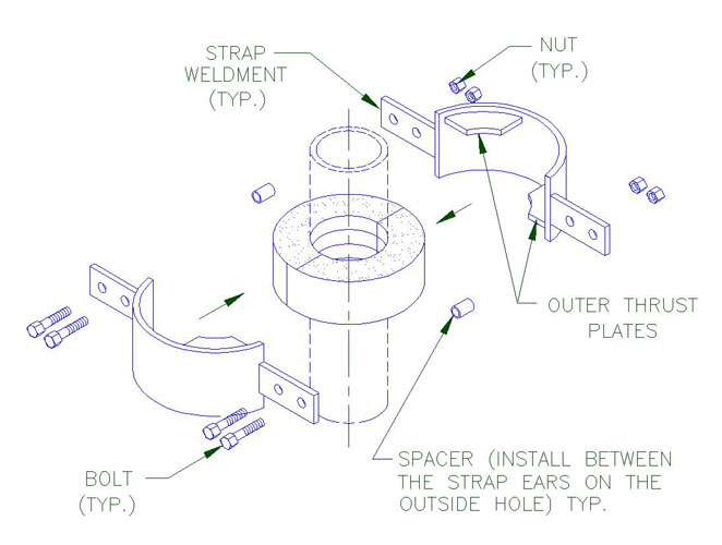
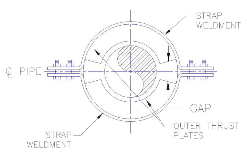
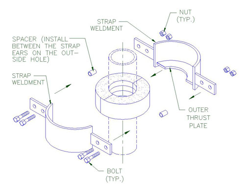
3. A) Assemble strap weldments (strap with shop welded outer thrust plates) and line up the bolt holes.
B) Install the bolts, spacers, lock washers and nuts as shown.
C) Hand tighten nuts before applying the specified torque.
D) Select torque value that correspond with the pipe size and model designation of the unit shown on Table 1. During tightening, it is recommended that the nut is turned rather than the bolt head and that the bolts be crosstorqued until the required torque has been achieved to obtain an even pressure on the structural insulation. To ensure that the bolts are properly crosstorqued by checking the spacing (B) between the ears to be approximately the same.
Note:
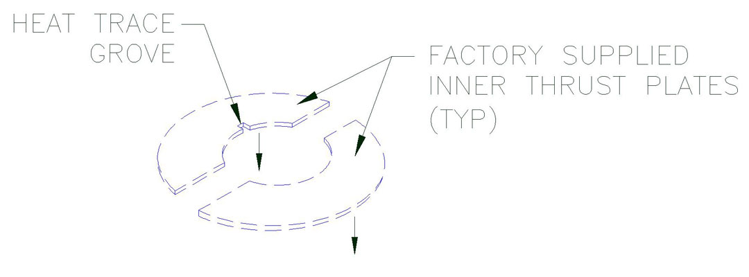
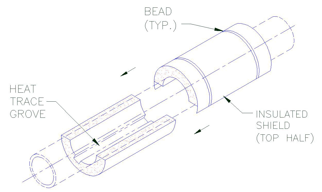
When models include heat trace groves, the number and location may vary. Check with design drawings for exact number and location. Ensure that the heat tracing cable is properly positioned inside the grove of the shield.
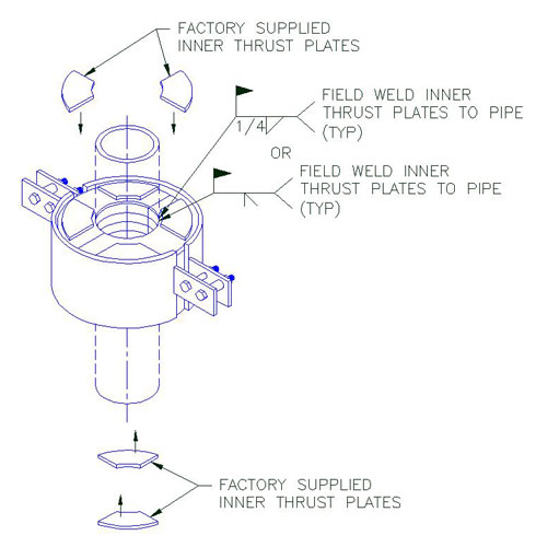
4. A) Locate and position factory supplied inner thrust plates (two on each side of the assembly) on the pipe. See below for locating and positioning the inner thrust plates on the pipe. When properly positioned weld them to the pipe as shown.
Note:
In order to act properly as designed, it is important that there is a zero clearance between the inner thrust plates and structural insert. It is recommended that the inner thrust plates be clamped tight against the structural insert before welding and remained clamped until the weld has completely colled-off to avoid or minimize shrinkage and/or distortion due to welding. If ther eis axial clearance, cut galvanied sheet metal shims to the same outline as the inner thrust plates and isntall them to reduce this clearance to zero.
Inner Thrust Plate Detail
Section A-A
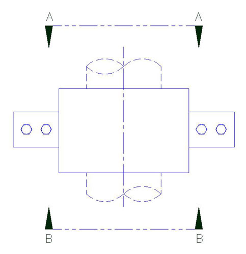
Elevation
Section B-B
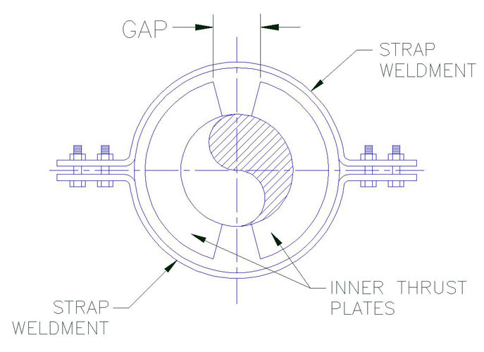
Notes:
1. Located the inner thrust plates on the side of the assembly directly opposite the outer thrust plates located on the
other side of the unit at all times (see sections A-A and B-B).
2. Position the inner thrust plate to provide equal clearance (*) between the edges of the inner thrust plate and the
two adjacent outer thrust plates as shown above.
* Gap tolerance
– 2 1/2″ thick insulation and less + 1/8″
– Greater than 2 1/2″ thick insulation + 1/4″
| Table 1 Bolt Torque |
||||
| Pipe Size | E2000 Series | E2100 Series | E2200 Series | E2300 Series |
| Bolt Torque (FT-LBS) |
Bolt Torque (FT-LBS) |
Bolt Torque (FT-LBS) |
Bolt Torque (FT-LBS) |
|
| 1 | 3-5 | 3-5 | 3-5 | |
| 1.5 | 3-5 | 3-5 | 5-7 | |
| 2 | 3-5 | 3-5 | 8-10 | |
| 2.5 | 3-5 | 3-5 | 8-10 | |
| 3 | 3-5 | 8-10 | 13-15 | |
| 3.5 | 3-5 | 8-10 | 13-15 | |
| 4 | 3-5 | 8-10 | 13-15 | |
| 5 | 5-7 | 13-15 | 18-20 | |
| 6 | 6-8 | 13-15 | 23-25 | |
| 8 | 8-10 | 18-20 | 28-30 | |
| 10 | 13-15 | 28-30 | 43-45 | |
| 12 | 13-15 | 28-30 | 43-45 | 58-60 |
| 14 | 18-20 | 38-40 | 58-60 | 73-75 |
| 16 | 18-20 | 38-40 | 58-60 | 88-90 |
| 18 | 23-25 | 48-50 | 73-75 | 98-100 |
| 20 | 23-25 | 48-50 | 73-75 | 98-100 |
| 24 | 23-25 | 56-60 | 88-90 | 118-120 |
E1000 through E1300 Pre-Insulated Riser Clamp Installation Instructions
Installation Steps
1. A) Position one half of the insulated shield (insulating structural material and sheet metal jacket) on the pipe at the desired location as shown.
2. A) Gently slide the other half of the insulated shield with the overlapping jacket into position over the previously located half shield.
3. A) Assemble strap weldments (strap with shop welded outer thrust plates) and line up the bolt holes.
B) Install the bolts, spacers, lock washers and nuts as shown.
C) Hand tighten nuts before applying the specified torque.
D) Select torque value that correspond with the pipe size and model designation of the unit shown on Table 1. During tightening, it is recommended that the nut is turned rather than the bolt head and that the bolts be crosstorqued until the required torque has been achieved to obtain an even pressure on the structural insulation. To ensure that the bolts are properly crosstorqued by checking the spacing (B) between the ears to be approximately the same.
Note:
When models include heat trace groves, the number and location may vary. Check with design drawings for exact number and location. Ensure that the heat tracing cable is properly positioned inside the grove of the shield.
4. Locate and position factory supplied inner thrust plates on the pipe. See sheet 3 for locating and positioning the inner thrust plates on the pipe. When properly positioned, weld them to the pipe as shown (see Table 1).
Note:
In order to act properly as designed, it is important that there is a zero clearance between the inner thrust plates and structural insert. It is recommended that the inner thrust plates be clamped tight against the structural insert before welding and remained clamped until the weld has completely colled-off to avoid or minimize shrinkage and/or distortion due to welding. If there is axial clearance, cut galvanized sheet metal shims to the same outline as the inner thrust plates and install them to reduce this clearance to zero.
Inner Thrust Plate Detail
Notes:
1. Located the inner thrust plates on the top side of the assembly and offest 90° fromt he location of the outer
plates which are locate dont he other side of the unit.
2. Position the inner thrust plate to provide equal clearance between the edges of the inner thrust plates as shown
above.
* Gap tolerance:
– 2 1/2″ thick insulation and less + 1/8″
– Greater than 2 1/2″ thick insulation + 1/4″
| Table 1 Bolt Torque |
||||
| Pipe Size | E1000-E10130 | E1100-E1130 | E1200-E1230 | E1300-E1330 |
| Bolt Torque (FT-LBS) |
Bolt Torque (FT-LBS) |
Bolt Torque (FT-LBS) |
Bolt Torque (FT-LBS) |
|
| 3/4 | 3-5 | 3-5 | 3-5 | |
| 1 | 3-5 | 3-5 | 3-5 | |
| 1.25 | 3-5 | 3-5 | 5-7 | |
| 1.5 | 3-5 | 3-5 | 5-7 | |
| 2 | 3-5 | 3-5 | 8-10 | |
| 2.5 | 3-5 | 3-5 | 8-10 | |
| 3 | 3-5 | 8-10 | 13-15 | |
| 3.5 | 3-5 | 8-10 | 13-15 | |
| 4 | 3-5 | 8-10 | 13-15 | |
| 5 | 5-7 | 13-15 | 18-20 | |
| 6 | 6-8 | 13-15 | 23-25 | |
| 8 | 8-10 | 18-20 | 28-30 | |
| 10 | 13-15 | 28-30 | 43-45 | |
| 12 | 13-15 | 28-30 | 43-45 | 58-60 |
| 14 | 18-20 | 38-40 | 58-60 | 73-75 |
| 16 | 18-20 | 38-40 | 58-60 | 88-90 |
| 18 | 23-25 | 48-50 | 73-75 | 98-100 |
| 20 | 23-25 | 48-50 | 73-75 | 98-100 |
| 24 | 23-25 | 56-60 | 88-90 | 118-120 |
D6000 through D6300 Pre-Insulated 2 Rod Hanger Installation Instructions
Installation Steps

1. Position the bottom half of the insulated hanger shield (insulating structural material and sheet metal jacket) on the pipe at the desired location as shown.
 2. A) Gently slide into position the top half of the insulated hanger shield over the bottom half shield as shown. 3. A) Place the straps into position (between the beads) and line up the bolt holes. B) Install the rods through the strap ears, lock washers, nuts and hand tighten. C) Apply torque value on the nuts. D) Select torque value that correspond with the pipe size and model designation of the unit shown on Table 1. When tightening, it is recommended that the nut is turned rather than the rod and that the rod be cross torqued until the required torqued has been achieved to obtain an even pressure on the structural insu-lation. E) To ensure that the bolts are properly cross-torque by checking spacing (B) between the ears shall be approximately the same (see Figure B). Note: When models include heat trace groves, the number and location may vary. Check with design drawings for exact number and location. Ensure that the heat tracing cable is properly positioned inside the grove of the shield.
|
|||||||||||||||||||||||||||||||||||||||||||||||||||||||||||||||||||||||||||||||||||||||||||||||||||||||||
|
|||||||||||||||||||||||||||||||||||||||||||||||||||||||||||||||||||||||||||||||||||||||||||||||||||||||||

D4000 through D5000 Pre-Insulated 2 Rod Hanger Installation Instructions
Installation Steps
1. A) Position the bottom half of the insulated hanger shield (insulating structural material and sheet metal jacket) on the pipe at the desired location as shown.

2. A) Gently slide into position the top half of the insulated hanger shield over the bottom half shield as shown.
Note: When models include heat trace groves, the number and location may vary. Check with design drawings for exact number and location. Ensure that the heat tracing cable is properly positioned inside the grove of the shield.
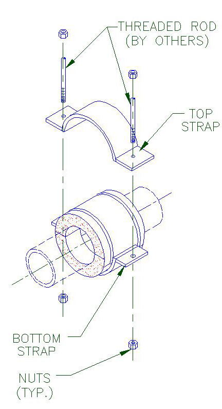
3. A) Position straps between the beads.
B) Install the threaded rod (by others), lockwashers and nuts and hand tighten.
C) Apply torque on the bolts.
D) Select torque value that correspond with the pipe size and model designation of the unit shown on Table 1.Below when tightening, it is recommended that the bolts are cross torqued until the required torqued has been achieved to obtain an even pressure on the structural insulation.
E) To ensure that the bolts are properly cross-torqued by checking spacing “B” between the ears shall be approximately the same (see Figure B).

Figure B
| Table 1 Bolt Torque |
||||
| D4000 Series | D5000 Series | |||
| Pipe Size | Bolt Torque (FT-LBS) |
Bolt Torque (FT-LBS) |
||
| 1/2″ | 1-3 | 1-3 | ||
| 3/4″ | 1-3 | 1-3 | ||
| 1″ | 1-3 | 1-3 | ||
| 1 1/4″ | 1-3 | 1-3 | ||
| 1 1/2″ | 1-3 | 1-3 | ||
| 2″ | 2-4 | 2-4 | ||
| 2 1/2″ | 2-4 | 2-4 | ||
| 3″ | 3-5 | 3-5 | ||
| 3 1/2″ | 3-5 | 3-5 | ||
| 4″ | 3-5 | 3-5 | ||
D1000 through D3300 Pre-Insulated 2 Bolt Hanger Installation Instructions
Installation Steps
Model D1000-D2000
1. A) Position the bottom half of the insulated hanger shield (insulating structural material and sheet metal jacket) on the pipe at the desired location.
B) Ensure that the bottom half shield is located under the pipe as shown below (Figure A).

Model D3000 – D3300
2. A) Gently slide into position the top half of the insulated hanger shield over the bottom half shield as shown.
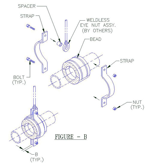
3. A) Place the straps into position (between the beads) and line up the bolt holes.
B) Install the bolts, through the strap ears, spacer, weldless eye nut, lock washers and nuts and hand tighten nuts.
C) Apply torque value on the bolts. Select torque value that correspond with the pipe size and model designation of the unit as shown on below, (Table 1 for model D1000-D2000, Table 2 for model D3000-D3300)
D) When tightening it is recommended that the nut is turned rather than the bolt head and that the bolts be cross-torqued until the required torque has been achieved to obtain an even pressure on the structural insulation (structural inserts for model D3000-D3300).
E) Ensure that the bolts are properly cross torqued by checking spacing (B) between the ears to be approximately the same (see figure B).
Note: When models include heat trace groves, the number and location may vary. Check with design drawings for exact number and location.
| Table 1 Bolt Torque |
|||||
| D1000 (Series) | D2000 (Series) | D1000 (Series) | D2000 (Series) | ||
| Pipe Size | Bolt Torque (FT – LBS) |
Bolt Torque (FT – LBS) |
Pipe Size | Bolt Torque (FT – LBS) |
Bolt Torque (FT – LBS) |
| 1/2″ | 1-3 | 1-3 | 2 1/2″ | 2-4 | 2-4 |
| 3/4″ | 1-3 | 1-3 | 3″ | 3-5 | 3-5 |
| 1″ | 1-3 | 1-3 | 3 1/2″ | 3-5 | 3-5 |
| 1 1/4″ | 1-3 | 1-3 | 4″ | 3-5 | 3-5 |
| 1 1/2″ | 1-3 | 1-3 | 6″ | 3-5 | 3-5 |
| 2″ | 2-4 | 2-4 | |||
| Table 2 Bolt Torque |
||||
| D3000 Series | D3100 Series | D3200 Series | D3300 Series | |
| Pipe Size | Bolt Torque (FT – LBS) |
Bolt Torque (FT – LBS) |
Bolt Torque (FT – LBS) |
Bolt Torque (FT – LBS) |
| 1 | 1-3 | 1-3 | 1-3 | 1-3 |
| 1.5 | 1-3 | 1-3 | 1-3 | 1-3 |
| 2 | 1-3 | 1-3 | 1-3 | 1-3 |
| 2.5 | 1-3 | 1-3 | 1-3 | 1-3 |
| 3 | 1-3 | 1-3 | 1-3 | 1-3 |
| 3.5 | 1-3 | 1-3 | 1-3 | 1-3 |
| 4 | 1-3 | 1-3 | 1-3 | 1-3 |
| 5 | 8-10 | 8-10 | 8-10 | 8-10 |
| 6 | 8-10 | 8-10 | 8-10 | 8-10 |
| 8 | 8-10 | 8-10 | 20-22 | 20-22 |
| 10 | 13-15 | 13-15 | 28-30 | 28-30 |
| 12 | 13-15 | 13-15 | 28-30 | 28-30 |
| 14 | 13-15 | 13-15 | 28-30 | 28-30 |
| 16 | 13-15 | 13-15 | 28-30 | 28-30 |
| 18 | 13-15 | 13-15 | 28-30 | 28-30 |
| 20 | 13-15 | 13-15 | 28-30 | 48-50 |
| 24 | 13-15 | 13-15 | 28-30 | 48-50 |
| 26 | 13-15 | 13-15 | 28-30 | 48-50 |
| 28 | 13-15 | 13-15 | 28-30 | 48-50 |
| 30 | 13-15 | 13-15 | 28-30 | 48-50 |
| 32 | ||||
| 36 | 33-35 | 42-44 | ||
| 42 | ||||
C4000 through C4300 Pre-Insulated Positive Pipe Anchor
Installation Steps
1. A) Center the base weldment assembly (bottom strap with shop welded outer thrust plates) under the applicable support location on the pipe section as shown.
2. A) Insert the lower half shield (structural insulation material and sheet metal jacket) between the outer thrust plates and under the pipe as shown.
3. A) Place the upper half shield (structural insulation material and sheet metal jacket) over the pipe and lower half shield installed in Step 2 as shown.
4. A) Assemble top strap weldment assembly. Top strap with shop welded outer thrust plates over the upper half shield and install the bolts through the clamp ears with nuts on top.
B) Apply the torque on the bolts, select torque value that correspond with the pipe size and model designation of the unit shown on Table 1 below. During tightening, it is recommended that the nut is turned rather than the bolt head and that the bolts be cross-torqued until the required torque has been achieved to obtain an even pressure on the structural insulation.
C) Ensure that the bolts are properly cross-torqued. by checking the spacing “B” between the ears to be approximately the same.
5. A) Locate and position factory supplied inner thrust plates (two on each side of the assembly) on the pipe. Locate and position the inner thrust plates on the pipe. When properly positioned weld them to the pipe shown (see Table 1 for the weld size.)
6. A) Weld base of anchor assembly to support member as shown. Select “W” (Weld Size) that correspond with the pipe size and model designation of the unit. Shown on Table 1.
Note:
In order to act properly as designed, it is important that there is a zero clearance between the inner thrust plates and structural insert. It is recommended that the inner thrust plates be clamped tight against the structural insert before welding and remained clamped until the weld has completely cooled off to avoid or minimize shrinkage and/or distortion due to welding. If theren is axial clearance, cut galvanized sheet metal shims to the same outline as the inner thrust plates and install them to reduce this clearance to zero.
Inner Thrust Plate Detail
Section A-A
Elevation
Section B-B
Section C-C
Notes:
1. Located the inner thrust plates on the side of the assembly directly opposite the outer thrust plates located on the other side of the unit at all times (see sections A-A and B-B). DO not install inner thrust plates directly over the outer thrust plates.
2. Position the inner thrust plate to provide equal gap (*) between the edges of the inner thrust plate and the two adjacent outer thrust plates as shown above.
3. Insulator to fill gaps as shown with loose insulation before installing pipe insulation.
| Table 1 Bolt Torque & Weld Size (W) | ||||||||
| Pipe Size | ||||||||
(FT-LBS) |
(FT-LBS) |
(FT-LBS) |
(FT-LBS) |
|||||
| 1″ | 5-10 | 3/16 | 10-15 | 3/16 | 10-15 | 1/4 | 10-15 | 1/4 |
| 1.25″ | 5-10 | 3/16 | 10-15 | 3/16 | 10-15 | 1/4 | 10-15 | 1/4 |
| 1.5″ | 5-10 | 3/16 | 10-15 | 3/16 | 10-15 | 1/4 | 10-15 | 1/4 |
| 2 | 5-10 | 3/16 | 10-15 | 3/16 | 10-15 | 1/4 | 10-15 | 1/4 |
| 3″ | 5-10 | 3/16 | 10-15 | 3/16 | 10-15 | 1/4 | 10-15 | 1/4 |
| 4″ | 5-10 | 3/16 | 10-15 | 3/16 | 10-15 | 1/4 | 10-15 | 1/4 |
| 6″ | 5-10 | 3/16 | 10-15 | 3/16 | 20-30 | 1/4 | 10-15 | 1/4 |
| 8″ | 5-10 | 3/16 | 10-15 | 3/16 | 20-30 | 1/4 | 15-20 | 1/4 |
| 10″ | 10-20 | 1/4 | 20-30 | 1/4 | 20-30 | 1/4 | 15-20 | 1/4 |
| 12″ | 10-20 | 1/4 | 20-30 | 1/4 | 20-30 | 1/4 | 20-23 | 1/4 |
| 14″ | 10-20 | 1/4 | 20-30 | 1/4 | 20-30 | 1/4 | 20-23 | 1/4 |
| 16″ | 10-20 | 1/4 | 20-30 | 1/4 | 30-50 | 1/4 | 30-32 | 5/16 |
| 18″ | 10-20 | 1/4 | 20-30 | 1/4 | 30-50 | 1/4 | 33-35 | 5/16 |
| 20″ | 10-20 | 1/4 | 20-30 | 1/4 | 30-50 | 1/4 | ||
| 24″ | 10-20 | 1/4 | 20-30 | 1/4 | 30-50 | 1/4 | ||
| 26″ | 10-20 | 1/4 | 20-30 | 1/4 | 30-50 | 1/4 | ||
| 28″ | 10-20 | 1/4 | 20-30 | 1/4 | 30-50 | 1/4 | ||
| 30″ | 30-50 | 1/4 | 50-60 | 1/4 | 60-75 | 5/16 | ||
| 36″ | 30-50 | 1/4 | 50-60 | 1/4 | 60-75 | 5/16 | ||
| 42″ | 30-50 | 1/4 | 50-60 | 1/4 | 60-75 | 5/16 | ||
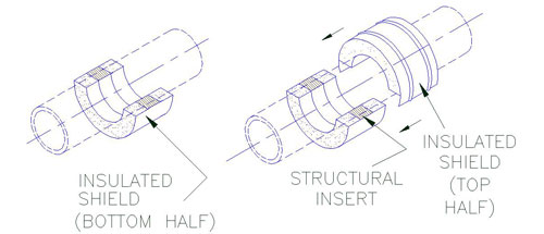
C3000 through C3300 Pre-Insulated Pipe Anchor Installation Instructions
Installation Steps
1. Position bottom half of the insulated shield into the base assembly. Ensure that the inserts are properly located over the strap by checking that:
A) Each end of shield shall have equal distance (C) from outer edge of strap (Figure A).
B) The 180° section of the bottom half shield shall be parallel to the support base (Figure B).
Slide the base assembly and insulated shield into position under the pipe at the applicable support location.
2. A) Lower the pipe onto the bottom half of the shield.
B) Slide the top shield into position.
C) Gently place the top strap into position above the bottom strap as shown and line up the bolt holes.
3. A) Install the bolts, lockwashers and nuts and hand tighten. For ease of bolt torquing, install the bolts with the nuts on top.
B) Apply torque on the bolts. Select torque value that correspond with the pipe size and model designation of the unit shown on Table 1. When tightening, it is recommended that the nut is turned rather than the bolt head and that the bolts are cross-torqued until the required torque has been achieved to obtain an even pressure on the structural insulation.
C) Ensure that the bolts are properly cross-torqued by checking the spacing “B” between the ears to be approximately the same (see Figure B).
4. When properly positioned, weld base assembly to steel support as shown. Select “W” (weld size) that correspond with the pipe size and model designation of the unit shown Table 1.
| Table 1
Bolt Torque & Weld Size (W) |
||||||||
| Pipe Size | ||||||||
| Bolt Torque (FT-LBS) |
Weld (W) Size | Bolt Torque (FT-LBS) |
Weld (W) Size | Bolt Torque (FT-LBS) |
Weld (W) Size |
Bolt Torque (FT-LBS) |
Weld (W) Size | |
| 1″ | 3-5 | 3/16″ | 3-5 | 3/16″ | 3-5 | 3/16″ | 3-5 | 3/16″ |
| 1.5″ | 3-5 | 3/16″ | 3-5 | 3/16″ | 3-5 | 3/16″ | 3-5 | 3/16″ |
| 2″ | 3-5 | 3/16″ | 3-5 | 3/16″ | 5-7 | 3/16″ | 3-5 | 3/16″ |
| 2.5″ | 3-5 | 3/16″ | 3-5 | 3/16″ | 3-5 | 3/16″ | 3-5 | 3/16″ |
| 3″ | 3-5 | 3/16″ | 3-5 | 3/16″ | 3-5 | 3/16″ | 3-5 | 3/16″ |
| 3.5″ | 3-5 | 3/16″ | 3-5 | 3/16″ | 8-10 | 3/16″ | 3-5 | 3/16″ |
| 4″ | 4-6 | 3/16″ | 7-9 | 3/16″ | 10-12 | 3/16″ | 7-9 | 3/16″ |
| 5″ | 4-6 | 3/16″ | 9-11 | 3/16″ | 13-15 | 3/16″ | 9-11 | 3/16″ |
| 6″ | 7-9 | 1/4″ | 13-15 | 1/4″ | 20-22 | 1/4″ | 13-15 | 1/4″ |
| 8″ | 9-11 | 1/4″ | 18-20 | 1/4″ | 27-29 | 1/4″ | 18-20 | 1/4″ |
| 10″ | 10-12 | 1/4″ | 21-23 | 1/4″ | 31-33 | 1/4″ | 21-23 | 1/4″ |
| 12″ | 11-13 | 1/4″ | 23-25 | 1/4″ | 34-36 | 1/4″ | 23-25 | 1/4″ |
| 14″ | 13-15 | 1/4″ | 26-28 | 1/4″ | 39-41 | 1/4″ | 26-28 | 1/4″ |
| 16″ | 18-20 | 1/4″ | 36-38 | 1/4″ | 54-56 | 1/4″ | 36-38 | 1/4″ |
| 18″ | 20-22 | 1/4″ | 40-42 | 1/4″ | 60-62 | 1/4″ | 40-42 | 1/4″ |
| 20″ | 21-23 | 1/4″ | 43-45 | 1/4″ | 64-66 | 1/4″ | 43-45 | 1/4″ |
| 24″ | 23-25 | 1/4″ | 45-47 | 1/4″ | 68-70 | 1/4″ | 45-47 | 1/4″ |
| 26″ | 20-25 | 1/4″ | 50-52 | 1/4″ | 75-77 | 1/4″ | 50-52 | 1/4″ |
| 28″ | 27-29 | 1/4″ | 54-56 | 1/4″ | 81-83 | 1/4″ | 54-56 | 1/4″ |
| 30″ | 39-41 | 1/4″ | 78-80 | 1/4″ | 118-120 | 1/4″ | 78-80 | 1/4″ |
| 32″ | 41-43 | 1/4″ | 82-84 | 1/4″ | 123-125 | 1/4″ | 82-84 | 1/4″ |
| 36″ | 46-48 | 1/4″ | 92-94 | 1/4″ | *138-140 | 1/4″ | 92-94 | 1/4″ |
| 42″ | 52-54 | 1/4″ | 103-105 | 1/4″ | *155-160 | 1/4″ | 103-105 | 1/4″ |
* = Requries A-325 Bolt Material
C2000 through C2030 Pre-Insulated Pipe Anchor Installation Instructions
Installation Steps

1. Position and slide anchor support between the center line of the pipe and the support member.
2. Weld the anchor support to the support member and to the pipe as shown (see Table 1 below for weld sizes and desired location).
| Table 1 | ||||||||
| Pipe Size | ||||||||
| 8″ | 3/16″ | 3/16″ | 3/16″ | 3/16″ | 3/16″ | 3/16″ | 3/16″ | 3/16″ |
| 10″ | 3/16″ | 3/16″ | 3/16″ | 3/16″ | 3/16″ | 3/16″ | 3/16″ | 3/16″ |
| 12″ | 3/16″ | 3/16″ | 3/16″ | 3/16″ | 3/16″ | 3/16″ | 3/16″ | 3/16″ |
| 14″ | 3/16″ | 3/16″ | 3/16″ | 3/16″ | 3/16″ | 3/16″ | ||
| 16″ | 3/16″ | 3/16″ | 3/16″ | 3/16″ | ||||
| 18″ | 3/16″ | 3/16″ | ||||||
| 20″ | 3/16″ | 3/16″ | ||||||
| 24″ | ||||||||
| 26″ | ||||||||
| 28″ | ||||||||
| 30″ | ||||||||
| 36″ | ||||||||
| 42″ | ||||||||
C1000 through C1030 Pre-Insulated Welded Pipe Anchor Installation Instructions
Installation Steps
1. Position and slide anchor support between the center line of the pipe and the support member.
2. When properly positoned, weld the anchor support to the support member and to the pipe as shown (see Table 1 below).
| Table 1 | ||||||||
| Pipe Size | ||||||||
| 2″ | 3/16″ | 3/16″ | 3/16″ | 3/16″ | 3/16″ | 3/16″ | 3/16″ | 3/16″ |
| 3″ | 3/16″ | 3/16″ | 3/16″ | 3/16″ | 3/16″ | 3/16″ | 3/16″ | 3/16″ |
| 4″ | 3/16″ | 3/16″ | 3/16″ | 3/16″ | 3/16″ | 3/16″ | ||
| 6″ | 3/16″ | 3/16″ | 3/16″ | 3/16″ | 3/16″ | 3/16″ | ||
| 8″ | 3/16″ | 3/16″ | 3/16″ | 3/16″ | ||||
| 10″ | 3/16″ | 3/16″ | 3/16″ | 3/16″ | ||||
| 12″ | 3/16″ | 3/16″ | 3/16″ | 3/16″ | ||||
| 14″ | 3/16″ | 3/16″ | ||||||
| 16″ | 3/16″ | 3/16″ | ||||||
| 18″ | ||||||||
| 20″ | ||||||||
| 24″ | ||||||||
| 26″ | ||||||||
| 28″ | ||||||||
| 30″ | ||||||||
| 36″ | ||||||||
| 42″ | ||||||||
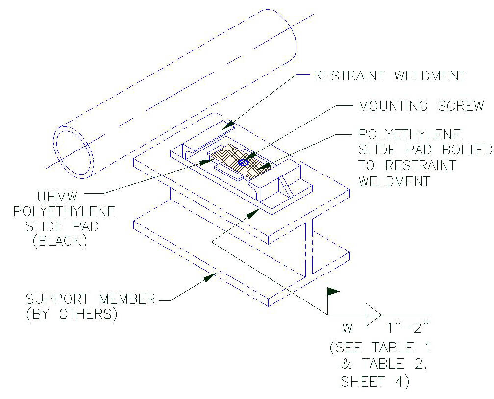
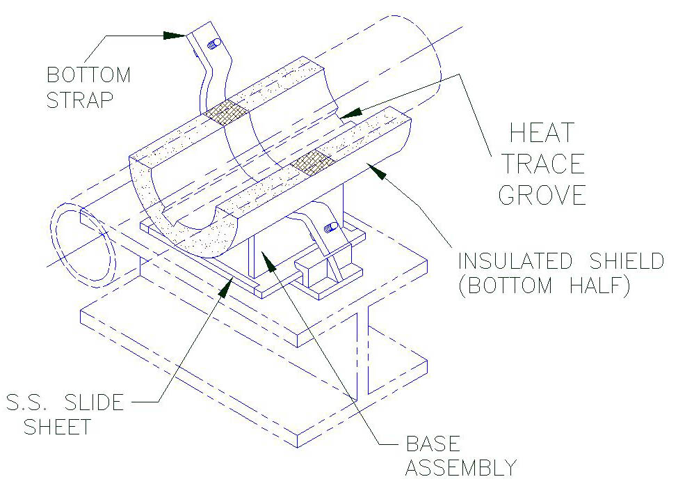
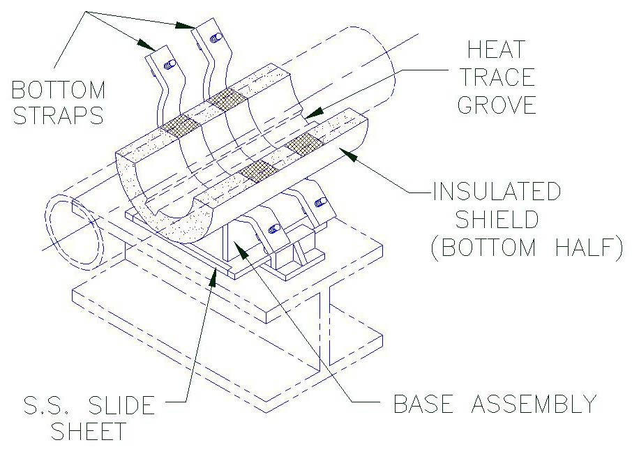
B7000 through B8300 Pre-Insulated Installation Instructions
Installation Steps
1. A) Remove the mounting screw from the slide pad and slide base restraint weldment.
B) Temporarily separate the slide pad from the restraint weldment.
C) Locate and position the restraint weldment on the steel support to meet the required piping analysis cold settings (see below for P.S.I. recommended cold settings). Please note that required piping analysis cold settings governs over P.S.I. recommendations.
D) When properly positioned, weld restraint weldment to support steel as shown. Select (W) weld size that correspond with the pipe size and model designation of the unit.
E) Place slide pad on restraint weldment and install with the mounting screws.
Model B7000 – B7300
2. Position bottom half of the insulated shield into the base assembly. Ensure that the inserts are properly located over the straps by checking that:
A) Each end of shield shall have equal distance (C) from outer edge of strap (Figure A & A1).
B) The 180° section of the bottom half shield shall be parallel to the support base (Figure B).
Model: B8000 – B8300 Series
3. A) Slide the base assembly and bottom half shield under the pipe.
A) Each end of shield shall have equal distance (C) from outer edge of strap (Figure A & A1).
B) Position the base assembly on the restraint weldment to allow for anticipated axial travel (see below for P.S.I. recommended axial cold settings).
Note: When models include heat trace groves, the number and location may vary. Check with design drawings for exact number and location. Ensure that the heat tracing cable is properly positioned inside the grove of the shield.
Model: B7000 – B7300 Series
4. A) Slide the top half shield into position above the bottom-half shield.
B) Gently place the top strap into position above the bottom strap and line-up the bolt holes.
Model: B8000 – B8300 Series
5. A) Install the bolts, lockwashers and nuts and hand tighten. For ease of bolt torquing, install the bolts with the nuts on top.
B) Apply torque on the bolts. Select torque value that corresponds with the pipe size and model designation of the unit shown on table 1 for model B7000-B7300 and table 2 for B8000-B8300. When tightening, It is recommended that the nut is turned rather than the bolt head and that the bolts are cross-torqued until the required torque has been achieved to obtain an even pressure on the structural insulation.
C) Ensure that the bolts are properly cross-torqued by checking the spacing “B” between the ears to be approximately the same (see Figure B).
Note: These units are designed for specific axial travel. Prior to tightening of the bolts, the unit may require cold setting (see figure A & A1 for recommended axial cold setting instructions for this unit).
Completed Assembly
Model B7000 – B7300
Completed Assembly
Model B8000 – B8300
Axial Cold Settings
Position base assembly such that after the support has moved, the center line of the strap (marked by the center line) approximately matches the center line of the restraint weldment (Figure A & A1).
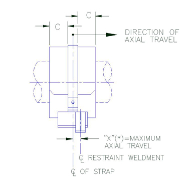
Figure A
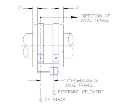
Figure A1
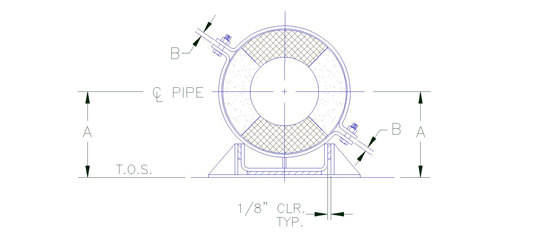
Figure B
| Table 1 Bolt Torque & Weld Size (W) |
||||||||
| Pipe Size | B7000 Series | B7100 Series | B7200 Series | B7300 Series | ||||
| Bolt Torque (FT – LBS) |
Weld (W) Size | Bolt Torque (FT – LBS) |
Weld (W) Size | Bolt Torque (FT – LBS) |
Weld (W) Size | Bolt Torque (FT – LBS) |
Weld (W) Size | |
| 1 | 3-5 | 3/16 | 3-5 | 3/16 | 3-5 | 3/16 | 3-5 | 3/16 |
| 1.5 | 3-5 | 3/16 | 3-5 | 3/16 | 3-5 | 3/16 | 3-5 | 3/16 |
| 2 | 3-5 | 3/16 | 3-5 | 3/16 | 3-5 | 3/16 | 3-5 | 3/16 |
| 2.5 | 3-5 | 3/16 | 5-7 | 3/16 | 5-7 | 3/16 | 3-5 | 3/16 |
| 3 | 3-5 | 3/16 | 7-9 | 3/16 | 7-9 | 3/16 | 3-5 | 3/16 |
| 3.5 | 3-5 | 3/16 | 8-10 | 3/16 | 8-10 | 3/16 | 6-8 | 3/16 |
| 4 | 3-5 | 3/16 | 10-12 | 3/16 | 10-12 | 3/16 | 7-9 | 3/16 |
| 5 | 3-5 | 3/16 | 13-15 | 3/16 | 13-15 | 3/16 | 9-11 | 3/16 |
| 6 | 7-9 | 1/4 | 20-22 | 1/4 | 20-22 | 1/4 | 13-15 | 1/4 |
| 8 | 9-11 | 1/4 | 27-29 | 1/4 | 27-29 | 1/4 | 18-20 | 1/4 |
| 10 | 10-12 | 1/4 | 31-33 | 1/4 | 31-33 | 1/4 | 21-23 | 1/4 |
| 12 | 11-13 | 1/4 | 34-37 | 1/4 | 34-37 | 1/4 | 23-25 | 1/4 |
| 14 | 13-15 | 1/4 | 39-41 | 1/4 | 39-41 | 1/4 | 26-28 | 1/4 |
| 16 | 18-20 | 1/4 | 54-56 | 1/4 | 54-56 | 1/4 | 36-38 | 1/4 |
| 18 | 20-22 | 1/4 | 60-62 | 1/4 | 60-62 | 1/4 | 40-42 | 1/4 |
| 20 | 21-23 | 1/4 | 64-66 | 1/4 | 64-66 | 1/4 | 43-45 | 1/4 |
| 24 | 23-25 | 1/4 | 68-70 | 1/4 | 68-70 | 1/4 | 45-47 | 1/4 |
| 26 | 25-27 | 1/4 | 75-77 | 1/4 | 75-77 | 1/4 | 50-52 | 1/4 |
| 28 | 27-29 | 1/4 | 81-83 | 1/4 | 81-83 | 1/4 | 54-56 | 1/4 |
| 30 | 39-41 | 1/4 | 118-120 | 1/4 | 118-120 | 1/4 | 78-80 | 1/4 |
| 32 | 41-43 | 1/4 | 123-125 | 1/4 | 123-125 | 1/4 | 82-84 | 1/4 |
| 36 | 46-48 | 1/4 | *138-140 | 1/4 | *135-140 | 1/4 | 92-84 | 1/4 |
| 42 | 52-54 | 1/4 | *155-157 | 1/4 | *155-157 | 1/4 | 1/4 | |
| * Requires A325 Bolt Material | ||||||||
| Table 2 Bolt Torque & Weld Size (W) |
||||||||
| Pipe Size | B8000 Series | B8100 Series | B8200 Series | B8300 Series | ||||
| Bolt Torque (FT – LBS) |
Weld (W) Size | Bolt Torque (FT – LBS) |
Weld (W) Size | Bolt Torque (FT – LBS) |
Weld (W) Size | Bolt Torque (FT – LBS) |
Weld (W) Size | |
| 1 | 3-5 | 3/16 | 3-5 | 3/16 | 3-5 | 3/16 | 3-5 | 3/16 |
| 1.5 | 3-5 | 3/16 | 3-5 | 3/16 | 3-5 | 3/16 | 3-5 | 3/16 |
| 2 | 3-5 | 3/16 | 3-5 | 3/16 | 3-5 | 3/16 | 3-5 | 3/16 |
| 2.5 | 3-5 | 3/16 | 3-5 | 3/16 | 3-5 | 3/16 | 3-5 | 3/16 |
| 3 | 3-5 | 3/16 | 3-5 | 3/16 | 3-5 | 3/16 | 3-5 | 3/16 |
| 3.5 | 3-5 | 3/16 | 3-5 | 3/16 | 3-5 | 3/16 | 3-5 | 3/16 |
| 4 | 3-5 | 3/16 | 3-5 | 3/16 | 5-7 | 3/16 | 3-5 | 3/16 |
| 5 | 3-5 | 3/16 | 3-5 | 3/16 | 7-9 | 3/16 | 3-5 | 3/16 |
| 6 | 3-5 | 1/4 | 7-9 | 1/4 | 10-12 | 1/4 | 7-9 | 1/4 |
| 8 | 3-5 | 1/4 | 9-11 | 1/4 | 13-15 | 1/4 | 9-11 | 1/4 |
| 10 | 5-7 | 1/4 | 10-12 | 1/4 | 16-18 | 1/4 | 10-12 | 1/4 |
| 12 | 6-8 | 1/4 | 12-14 | 1/4 | 17-19 | 1/4 | 12-14 | 1/4 |
| 14 | 7-9 | 1/4 | 13-15 | 1/4 | 20-22 | 1/4 | 13-15 | 1/4 |
| 16 | 9-11 | 1/4 | 18-20 | 1/4 | 27-29 | 1/4 | 18-20 | 1/4 |
| 18 | 10-12 | 1/4 | 20-22 | 1/4 | 30-32 | 1/4 | 20-22 | 1/4 |
| 20 | 11-13 | 1/4 | 21-23 | 1/4 | 32-34 | 1/4 | 21-23 | 1/4 |
| 24 | 11-13 | 1/4 | 23-25 | 1/4 | 34-36 | 1/4 | 23-25 | 1/4 |
| 26 | 13-15 | 1/4 | 25-27 | 1/4 | 38-40 | 1/4 | 25-27 | 1/4 |
| 28 | 13-15 | 1/4 | 27-29 | 1/4 | 40-42 | 1/4 | 27-29 | 1/4 |
| 30 | 20-22 | 1/4 | 39-41 | 1/4 | 59-61 | 1/4 | 39-41 | 1/4 |
| 32 | 20-22 | 1/4 | 41-43 | 1/4 | 61-63 | 1/4 | 41-43 | 1/4 |
| 36 | 23-25 | 1/4 | 46-48 | 1/4 | 68-70 | 1/4 | 46-48 | 1/4 |
| 42 | 26-28 | 1/4 | 52-54 | 1/4 | 77-79 | 1/4 | 51-53 | 1/4 |
B5000 through B6300 Pre-Insulated Installation Instructions
Installation Steps
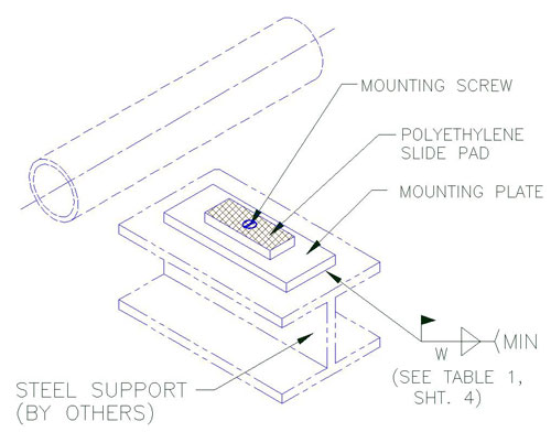
1. A) Remove the mounting screw from the slide pads and mounting plates.
B) Temporarily separate the slide pad from the mounting plate.
C) Locate and position the mounting plate on the steel support to meet the required piping analysis cold settings (see below, for P.S.I. recommended cold settings). Please note that required piping analysis cold settings governs over P.S.I. recommendations).
D) When properly positioned, weld mounting plate to support steel as shown. Select “w” (weld size) that correspond with the pipe size and model designation of the unit.
E) Place slide pad on mounting plate and install with the mounting screw.
Model: B5000 – B5300
2. Position bottom half of the insulated shield into the base assembly. Ensure that the inserts are properly located over the strap by checking that:
A) Each end of shield shall have equal distance (c) from outer edge of strap (Figure A & A1).
B) The 180° section of the bottom half shield shall be parallel to the support base (Figure B).
Model B6000 – B6300
3. A) Slide the base assembly and bottom half shield under the pipe.
B) position the base assembly on the mounting plate to allow for anticipated axial and lateral travel (see below for p.s.i. recommended axial and lateral cold settings).
Notes:
When models include heat trace groves, the number and location may vary. Check with design drawings for exact number and location. Ensure that the heat tracing cable is properly positioned inside the grove of the shield.
Model: B5000-B5300
4. A) Slide the top half shield into position above the bottom-half shield.
B) Gently place the top strap into position above the bottom strap and line-up the bolt holes.
Model: B6000-B6300
5. A) Install the bolts, lockwashers and nuts and hand tighten. For ease of bolt torquing, install the bolts with the nuts on top.
B) Apply torque on the bolts. Select torque value that corresponds with the pipe size and model designation of the unit shown on table 1 for model B3000-B3300 and table 2 for B4000-B4300. When tightening, it is recommended that the nut is turned rather than the bolt head and that the bolts are cross-torqued until the required torque has been achieved to obtain an even pressure on the structural insulation.
C) Ensure that the bolts are properly cross-torqued by checking the spacing “B” between the ears to be approximately the same (see Figure B).
Note:
These units are designed for specific axial travel. Prior to tightening of the bolts, the unit may require cold setting (see figure A & A1 for recommended axial cold setting instructions for this unit).
Completed Assembly
Model: B5000-B5300
Completed Assembly
Model: B6000-B6300
Axial & Lateral Cold Settings
A) Axial cold setting: Position base assembly such that after the support has moved, the center line of the strap (marked by the center line) approximately matches the center line of the slide pad (Figure A & A1).
B) Lateral cold setting: For lateral cold setting, match the center of the base assembly over the center of the slide pad assembly (Figure B).
| Table 1
Bolt Torque & Weld Size (W) |
||||||||
| Pipe Size | ||||||||
(FT-LBS) |
(FT-LBS) |
(FT-LBS) |
(FT-LBS) |
|||||
| 1″ | 3-5 | 3/16″ | 3-5 | 3/16″ | 3-5 | 3/16″ | 3-5 | 3/16″ |
| 1.5″ | 3-5 | 3/16″ | 3-5 | 3/16″ | 3-5 | 3/16″ | 3-5 | 3/16″ |
| 2″ | 3-5 | 3/16″ | 3-5 | 3/16″ | 3-5 | 3/16″ | 3-5 | 3/16″ |
| 2.5″ | 3-5 | 3/16″ | 3-5 | 3/16″ | 5-7 | 3/16″ | 3-5 | 3/16″ |
| 3″ | 3-5 | 3/16″ | 3-5 | 3/16″ | 7-9 | 3/16″ | 3-5 | 3/16″ |
| 3.5″ | 3-5 | 3/16″ | 6-8 | 3/16″ | 8-10 | 3/16″ | 6-8 | 3/16″ |
| 4″ | 3-5 | 3/16″ | 7-9 | 3/16″ | 10-12 | 3/16″ | 7-9 | 3/16″ |
| 5″ | 3-5 | 3/16″ | 9-11 | 3/16″ | 13-15 | 3/16″ | 9-11 | 3/16″ |
| 6″ | 7-9 | 1/4″ | 13-15 | 1/4″ | 20-22 | 1/4″ | 13-15 | 1/4″ |
| 8″ | 9-11 | 1/4″ | 18-20 | 1/4″ | 27-29 | 1/4″ | 18-20 | 1/4″ |
| 10″ | 10-12 | 1/4″ | 21-23 | 1/4″ | 31-33 | 1/4″ | 21-23 | 1/4″ |
| 12″ | 11-13 | 1/4″ | 23-25 | 1/4″ | 34-37 | 1/4″ | 23-25 | 1/4″ |
| 14″ | 13-15 | 1/4″ | 26-28 | 1/4″ | 39-41 | 1/4″ | 26-28 | 1/4″ |
| 16″ | 18-20 | 1/4″ | 36-38 | 1/4″ | 54-56 | 1/4″ | 36-38 | 1/4″ |
| 18″ | 20-22 | 1/4″ | 40-42 | 1/4″ | 60-62 | 1/4″ | 40-42 | 1/4″ |
| 20″ | 21-23 | 1/4″ | 43-45 | 1/4″ | 64-66 | 1/4″ | 43-45 | 1/4″ |
| 24″ | 23-25 | 1/4″ | 45-47 | 1/4″ | 68-70 | 1/4″ | 45-47 | 1/4″ |
| 26″ | 25-27 | 1/4″ | 50-52 | 1/4″ | 75-77 | 1/4″ | 50-52 | 1/4″ |
| 28″ | 27-29 | 1/4″ | 54-56 | 1/4″ | 81-83 | 1/4″ | 54-56 | 1/4″ |
| 30″ | 39-41 | 1/4″ | 78-80 | 1/4″ | 118-120 | 1/4″ | 78-80 | 1/4″ |
| 32″ | 41-43 | 1/4″ | 82-84 | 1/4″ | 123-125 | 1/4″ | 82-84 | 1/4″ |
| 36″ | 46-48 | 1/4″ | 92-94 | 1/4″ | *138-140 | 1/4″ | 92-94 | 1/4″ |
| 42″ | 52-54 | 1/4″ | 103-105 | 1/4″ | *155-157 | 1/4″ | 103-105 | 1/4″ |
* = Requries A-325 Bolt Material
| Table 2 Bolt Torque & Weld Size (W) | ||||||||
| Pipe Size | ||||||||
(FT-LBS) |
(FT-LBS) |
(FT-LBS) |
(FT-LBS) |
|||||
| 1″ | 3-5 | 3/16″ | 3-5 | 3/16″ | 3-5 | 3/16″ | 3-5 | 3/16″ |
| 1.5″ | 3-5 | 3/16″ | 3-5 | 3/16″ | 3-5 | 3/16″ | 3-5 | 3/16″ |
| 2″ | 3-5 | 3/16″ | 3-5 | 3/16″ | 3-5 | 3/16″ | 3-5 | 3/16″ |
| 2.5″ | 3-5 | 3/16″ | 3-5 | 3/16″ | 3-5 | 3/16″ | 3-5 | 3/16″ |
| 3″ | 3-5 | 3/16″ | 3-5 | 3/16″ | 3-5 | 3/16″ | 3-5 | 3/16″ |
| 3.5″ | 3-5 | 3/16″ | 3-5 | 3/16″ | 3-5 | 3/16″ | 3-5 | 3/16″ |
| 4″ | 3-5 | 3/16″ | 3-5 | 3/16″ | 5-7 | 3/16″ | 3-5 | 3/16″ |
| 5″ | 3-5 | 3/16″ | 3-5 | 3/16″ | 6-8 | 3/16″ | 3-5 | 3/16″ |
| 6″ | 3-5 | 1/4″ | 7-9 | 1/4″ | 10-12 | 1/4″ | 7-9 | 1/4″ |
| 8″ | 3-5 | 1/4″ | 9-11 | 1/4″ | 13-15 | 1/4″ | 9-11 | 1/4″ |
| 10″ | 5-7 | 1/4″ | 10-12 | 1/4″ | 16-18 | 1/4″ | 10-12 | 1/4″ |
| 12″ | 6-8 | 1/4″ | 11-13 | 1/4″ | 17-19 | 1/4″ | 11-13 | 1/4″ |
| 14″ | 7-9 | 1/4″ | 13-15 | 1/4″ | 20-22 | 1/4″ | 13-15 | 1/4″ |
| 16″ | 9-11 | 1/4″ | 18-20 | 1/4″ | 27-29 | 1/4″ | 18-20 | 1/4″ |
| 18″ | 10-12 | 1/4″ | 20-22 | 1/4″ | 30-32 | 1/4″ | 20-22 | 1/4″ |
| 20″ | 11-13 | 1/4″ | 21-23 | 1/4″ | 32-34 | 1/4″ | 21-23 | 1/4″ |
| 24″ | 11-13 | 1/4″ | 23-25 | 1/4″ | 34-36 | 1/4″ | 23-25 | 1/4″ |
| 26″ | 13-15 | 1/4″ | 25-27 | 1/4″ | 38-40 | 1/4″ | 25-27 | 1/4″ |
| 28″ | 13-15 | 1/4″ | 27-29 | 1/4″ | 40-42 | 1/4″ | 27-29 | 1/4″ |
| 30″ | 20-23 | 1/4″ | 39-41 | 1/4″ | 59-61 | 1/4″ | 39-41 | 1/4″ |
| 32″ | 20-23 | 1/4″ | 41-43 | 1/4″ | 61-63 | 1/4″ | 41-43 | 1/4″ |
| 36″ | 23-25 | 1/4″ | 46-48 | 1/4″ | 69-71 | 1/4″ | 46-48 | 1/4″ |
| 42″ | 26-28 | 1/4″ | 52-54 | 1/4″ | 78-80 | 1/4″ | 52-54 | 1/4″ |
B3000 through B4300 Pre-Insulated Support Installation Instructions
Installation Steps
1. A) Remove the mounting screw from the slide pad and slide base restraint weldment.
B) Temporarily separate the slide pad from the restraint weldment.
C) Locate and position the restraint weldment on the steel support to meet the required piping analysis cold settings (see below for P.S.I. recommended cold settings). Please note that required piping analysis cold settings governs over P.S.I. recommendations.
D) When properly positioned, weld restraint weldment to support steel as shown. Select (W) weld size that correspond with the pipe size and model designation of the unit.
E) Place slide pad on restraint weldment and install with the mounting screws.
Model: B3000 – B3300
2. Position bottom half of the insulated shield into the base assembly. Ensure that the inserts are properly located over the strap(s) by checking that:
A) Each end of shield shall have equal distance (c) from outer edge of strap (Figure A or A1).
B) The 180° section of the bottom half shield shall be parallel to the support base (Figure 8).
Model: B4000-B4300
3. A) Slide the base assembly and bottom half shield under the pipe.
(B) Position the base assembly on the restraint weldment to allow for anticipated axial travel.
Notes:
When models include heat trace groves, the number and location may vary. Check with design drawings for exact number and location. Ensure that the heat tracing cable is properly positioned inside the grove of the shield.
Model: B3000 – B3300
4. A) Slide the top half shield into position above the bottom-half shield.
B) Gently place the top strap into position above the bottom strap and line-up the bolt holes.
Model: B4000-B4300
5. A) Install the bolts, lockwashers and nuts and hand tighten. For ease of bolt torquing, install the bolts with the nuts on top.
B) Apply torque on the bolts. Select torque value that corresponds with the pipe size and model designation of the unit shown on table 1 for model B3000-B3300 and table 2 for B4000-B4300. When tightening, it is recommended that the nut is turned rather than the bolt head and that the bolts are cross-torqued until the required torque has been achieved to obtain an even pressure on the structural insulation.
C) Ensure that the bolts are properly cross-torqued by checking the spacing “B” between the ears to be approximately the same (see Figure B).
Note:
These units are designed for specific axial travel. Prior to tightening of the bolts, the unit may require cold setting (see figure A & A1 for recommended axial cold setting instructions for this unit).
Completed Assembly
Model: B3000 – B3300
Completed Assembly
Model: B4000-B4300
Axial Cold Settings
A) Position base assembly such that after the support has moved, the center line of the strap (marked by the center line) approximately matches the center line of the restraint weldment (Figure A & A1).
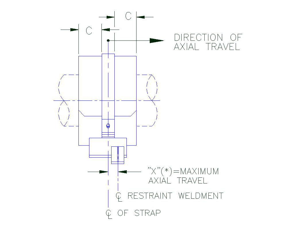
Figure A
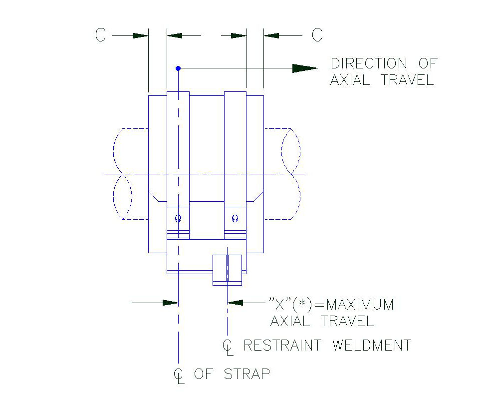
Figure A1
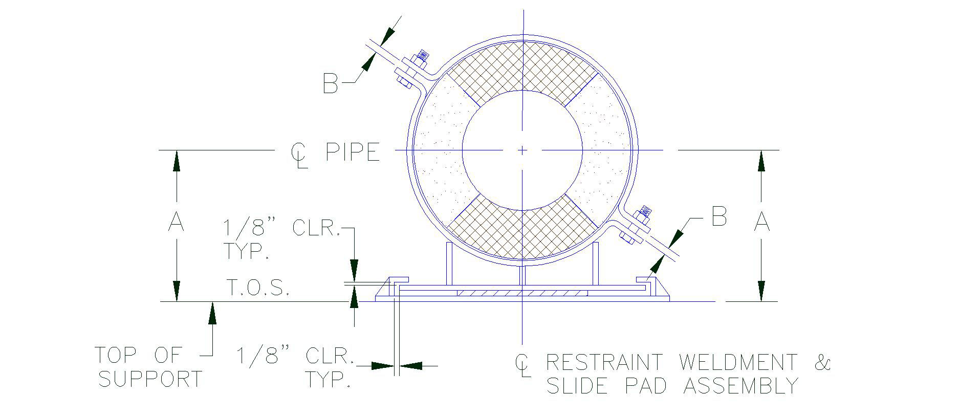
Figure B
| Table 1Bolt Torque & Weld Size (W) | ||||||||
| Pipe Size | ||||||||
(FT-LBS) |
(FT-LBS) |
(FT-LBS) |
(FT-LBS) |
|||||
| .5″ | 3-5 | 3/16″ | 3-5 | 3/16″ | 3-5 | 3/16″ | 3-5 | 3/16″ |
| 1″ | 3-5 | 3/16″ | 3-5 | 3/16″ | 3-5 | 3/16″ | 3-5 | 3/16″ |
| 1.5″ | 3-5 | 3/16″ | 3-5 | 3/16″ | 3-5 | 3/16″ | 3-5 | 3/16″ |
| 2″ | 3-5 | 3/16″ | 3-5 | 3/16″ | 5-7 | 3/16″ | 3-5 | 3/16″ |
| 2.5″ | 3-5 | 3/16″ | 3-5 | 3/16″ | 6-8 | 3/16″ | 3-5 | 3/16″ |
| 3″ | 3-5 | 3/16″ | 5-7 | 3/16″ | 7-9 | 3/16″ | 3-5 | 3/16″ |
| 3.5″ | 3-5 | 3/16″ | 6-8 | 3/16″ | 8-10 | 3/16″ | 6-8 | 3/16″ |
| 4″ | 3-5 | 3/16″ | 7-9 | 3/16″ | 11-13 | 3/16″ | 7-9 | 3/16″ |
| 5″ | 3-5 | 3/16″ | 9-11 | 3/16″ | 13-15 | 3/16″ | 9-11 | 3/16″ |
| 6″ | 7-9 | 1/4″ | 14-16 | 1/4″ | 20-22 | 1/4″ | 14-16 | 1/4″ |
| 8″ | 9-11 | 1/4″ | 18-20 | 1/4″ | 27-29 | 1/4″ | 18-20 | 1/4″ |
| 10″ | 11-13 | 1/4″ | 21-23 | 1/4″ | 32-34 | 1/4″ | 21-23 | 1/4″ |
| 12″ | 12-14 | 1/4″ | 23-25 | 1/4″ | 35-37 | 1/4″ | 23-25 | 1/4″ |
| 14″ | 13-15 | 1/4″ | 27-29 | 1/4″ | 40-42 | 1/4″ | 27-29 | 1/4″ |
| 16″ | 18-20 | 1/4″ | 37-39 | 1/4″ | 55-57 | 1/4″ | 37-39 | 1/4″ |
| 18″ | 20-22 | 1/4″ | 41-43 | 1/4″ | 61-63 | 1/4″ | 41-43 | 1/4″ |
| 20″ | 22-24 | 1/4″ | 43-45 | 1/4″ | 65-67 | 1/4″ | 43-45 | 1/4″ |
| 24″ | 23-25 | 1/4″ | 46-48 | 1/4″ | 69-71 | 1/4″ | 46-48 | 1/4″ |
| 26″ | 25-27 | 1/4″ | 51-53 | 1/4″ | 76-78 | 1/4″ | 51-53 | 1/4″ |
| 28″ | 27-29 | 1/4″ | 55-57 | 1/4″ | 82-84 | 1/4″ | 55-57 | 1/4″ |
| 30″ | 40-42 | 1/4″ | 80-82 | 1/4″ | 120-122 | 1/4″ | 80-82 | 1/4″ |
| 32″ | 42-44 | 1/4″ | 85-87 | 1/4″ | *127-129 | 1/4″ | 85-87 | 1/4″ |
| 36″ | 47-49 | 1/4″ | 93-95 | 1/4″ | *140-142 | 1/4″ | 93-95 | 1/4″ |
| 42″ | 53-55 | 1/4″ | 105-107 | 1/4″ | *158-160 | 1/4″ | 105-107 | 1/4″ |
| 48″ | 60-62 | 1/4″ | 120-122 | 1/4″ | *180-185 | 1/4″ | 120-122 | 1/4″ |
* = Requries A-325 Bolt Material
| Table 2Bolt Torque & Weld Size (W) | ||||||||
| Pipe Size | ||||||||
(FT-LBS) |
(FT-LBS) |
(FT-LBS) |
(FT-LBS) |
|||||
| 1″ | 3-5 | 3/16″ | 3-5 | 3/16″ | 3-5 | 3/16″ | 3-5 | 3/16″ |
| 1.5″ | 3-5 | 3/16″ | 3-5 | 3/16″ | 3-5 | 3/16″ | 3-5 | 3/16″ |
| 2″ | 3-5 | 3/16″ | 3-5 | 3/16″ | 3-5 | 3/16″ | 3-5 | 3/16″ |
| 2.5″ | 3-5 | 3/16″ | 3-5 | 3/16″ | 3-5 | 3/16″ | 3-5 | 3/16″ |
| 3″ | 3-5 | 3/16″ | 3-5 | 3/16″ | 3-5 | 3/16″ | 3-5 | 3/16″ |
| 3.5″ | 3-5 | 3/16″ | 3-5 | 3/16″ | 3-5 | 3/16″ | 3-5 | 3/16″ |
| 4″ | 3-5 | 3/16″ | 3-5 | 3/16″ | 5-7 | 3/16″ | 3-5 | 3/16″ |
| 5″ | 3-5 | 3/16″ | 3-5 | 3/16″ | 7-9 | 3/16″ | 3-5 | 3/16″ |
| 6″ | 3-5 | 1/4″ | 7-9 | 1/4″ | 10-12 | 1/4″ | 7-9 | 1/4″ |
| 8″ | 5-7 | 1/4″ | 9-11 | 1/4″ | 14-16 | 1/4″ | 9-11 | 1/4″ |
| 10″ | 5-7 | 1/4″ | 11-13 | 1/4″ | 16-18 | 1/4″ | 11-13 | 1/4″ |
| 12″ | 6-8 | 1/4″ | 12-14 | 1/4″ | 18-20 | 1/4″ | 12-14 | 1/4″ |
| 14″ | 7-9 | 1/4″ | 13-15 | 1/4″ | 20-22 | 1/4″ | 13-15 | 1/4″ |
| 16″ | 9-11 | 1/4″ | 18-20 | 1/4″ | 28-30 | 1/4″ | 18-20 | 1/4″ |
| 18″ | 10-12 | 1/4″ | 20-22 | 1/4″ | 31-33 | 1/4″ | 20-22 | 1/4″ |
| 20″ | 11-13 | 1/4″ | 22-24 | 1/4″ | 33-35 | 1/4″ | 22-24 | 1/4″ |
| 24″ | 11-13 | 1/4″ | 23-25 | 1/4″ | 34-36 | 1/4″ | 23-25 | 1/4″ |
| 26″ | 13-15 | 1/4″ | 25-27 | 1/4″ | 38-40 | 1/4″ | 25-27 | 1/4″ |
| 28″ | 14-16 | 1/4″ | 27-29 | 1/4″ | 41-43 | 1/4″ | 27-29 | 1/4″ |
| 30″ | 20-22 | 1/4″ | 40-42 | 1/4″ | 60-62 | 1/4″ | 40-42 | 1/4″ |
| 32″ | 21-23 | 1/4″ | 42-44 | 1/4″ | 62-64 | 1/4″ | 42-44 | 1/4″ |
| 36″ | 23-25 | 1/4″ | 47-49 | 1/4″ | 70-72 | 1/4″ | 47-49 | 1/4″ |
| 42″ | 26-28 | 1/4″ | 53-55 | 1/4″ | 79-81 | 1/4″ | 53-55 | 1/4″ |
B1000 through B2300 Pre-Insulated Support Installation Instructions
Installation Steps
1. A) Locate and position the restraint weld menton the steel support member as shown.
B) When properly positioned, weld the restraint weldment to support steel as shown.
Model B1000 – B1300

Model: B2000-B2300
2. Position bottom half of the insulated shield into the base assembly. Ensure that the inserts are properly located over the straps by checking that:
A) Each end of shield shall have equal distance (c) from outer edge of strap (Figure A).
B) The 180° section of the bottom half shield shall be parallel to the support base (Figure B).
3. A) Slide the base assembly and bottom half shield under the pipe.
B) Position the base assembly on the restraint weldment to allow for anticipated axial travel.
Notes: When models include heat trace groves, the number and location may vary. Check with design drawings for exact number and location. Ensure that the heat tracing cable is properly positioned inside the grove of the shield.
Model: B1000-B1300 Series

Model: B2000 – B2300 Series
4. A) Slide the top half shield into position above the bottom-half shield.
B) Gently place the top strap(s) into position above the bottom strap and line-up the bolt holes.
5. A) Install the bolts, lockwashers and nuts and hand tighten. For ease of bolt torquing, install the bolts with the nuts on top.
B) Apply torque on the bolts. Select torque value that corresponds with the pipe size and model designation of the unit shown on table 1 for model B1000-B1300 and table 2 for B2000-B2300. When tightening, it is recommended that the nut is turned rather than the bolt head and that the bolts are cross-torqued until the required torque has been achieved to obtain an even pressure on the structural insulation.
C) Ensure that the bolts are properly cross-torqued by checking the spacing “b” between the ears to be approximately the same (see Figure B).
Note: These units are designed for specific axia and laterall travel. Prior to tightening of the bolts, the unit may require cold setting. See figure A – A1 & B. For recommended axial and lateral cold setting instruction for this unit.
Completed Assembly
Model B1000 – B1300
Completed Assembly
Model B2000 – B2300
Recommended Axial and Lateral Cold Settings
A) Axial cold setting: Position base assembly such that after the support has moved, the center line of the strap ( marked by the center line) approximately matches the center line of the slide pad.
Axial Cold Setting
Model B1000-B1300
Figure A
Axial Cold Setting
Model B2000-B2300
Figure A1
Lateral Cold Setting
Figure B
B) Lateral cold setting: Match the center of the base assembly over the center of the slide pad assembly (Figure B)
| Table 1
Bolt Torque & Weld Size (W) |
||||||||
| Pipe Size | ||||||||
(FT-LBS) |
(FT-LBS) |
(FT-LBS) |
(FT-LBS) |
|||||
| .5″ | 3-5 | 3/16″ | 3-5 | 3/16″ | 3-5 | 3/16″ | 3-5 | 3/16″ |
| 1″ | 3-5 | 3/16″ | 3-5 | 3/16″ | 3-5 | 3/16″ | 3-5 | 3/16″ |
| 1.5″ | 3-5 | 3/16″ | 3-5 | 3/16″ | 3-5 | 3/16″ | 3-5 | 3/16″ |
| 2″ | 3-5 | 3/16″ | 3-5 | 3/16″ | 3-5 | 3/16″ | 3-5 | 3/16″ |
| 2.5″ | 3-5 | 3/16″ | 3-5 | 3/16″ | 3-5 | 3/16″ | 3-5 | 3/16″ |
| 3″ | 3-5 | 3/16″ | 3-5 | 3/16″ | 3-5 | 3/16″ | 3-5 | 3/16″ |
| 3.5″ | 3-5 | 3/16″ | 3-5 | 3/16″ | 8-10 | 3/16″ | 3-5 | 3/16″ |
| 4″ | 4-6 | 3/16″ | 7-9 | 3/16″ | 10-12 | 3/16″ | 7-9 | 3/16″ |
| 5″ | 4-6 | 3/16″ | 9-11 | 3/16″ | 13-15 | 3/16″ | 9-11 | 3/16″ |
| 6″ | 7-9 | 1/4″ | 13-15 | 1/4″ | 20-22 | 1/4″ | 13-15 | 1/4″ |
| 8″ | 9-11 | 1/4″ | 18-20 | 1/4″ | 27-29 | 1/4″ | 18-20 | 1/4″ |
| 10″ | 10-12 | 1/4″ | 21-23 | 1/4″ | 31-33 | 1/4″ | 21-23 | 1/4″ |
| 12″ | 11-13 | 1/4″ | 23-25 | 1/4″ | 34-36 | 1/4″ | 23-25 | 1/4″ |
| 14″ | 13-15 | 1/4″ | 26-28 | 1/4″ | 39-41 | 1/4″ | 26-28 | 1/4″ |
| 16″ | 18-20 | 1/4″ | 36-38 | 1/4″ | 54-56 | 1/4″ | 36-38 | 1/4″ |
| 18″ | 20-22 | 1/4″ | 40-42 | 1/4″ | 60-62 | 1/4″ | 40-42 | 1/4″ |
| 20″ | 21-23 | 1/4″ | 43-45 | 1/4″ | 64-66 | 1/4″ | 43-45 | 1/4″ |
| 24″ | 23-25 | 1/4″ | 45-47 | 1/4″ | 68-70 | 1/4″ | 45-47 | 1/4″ |
| 26″ | 20-25 | 1/4″ | 50-52 | 1/4″ | 75-77 | 1/4″ | 50-52 | 1/4″ |
| 28″ | 27-29 | 1/4″ | 54-56 | 1/4″ | 81-83 | 1/4″ | 54-56 | 1/4″ |
| 30″ | 39-41 | 1/4″ | 78-80 | 1/4″ | 118-120 | 1/4″ | 78-80 | 1/4″ |
| 32″ | 41-43 | 1/4″ | 82-84 | 1/4″ | 123-125 | 1/4″ | 82-84 | 1/4″ |
| 36″ | 46-48 | 1/4″ | 92-94 | 1/4″ | *138-140 | 1/4″ | 92-94 | 1/4″ |
| 42″ | 52-54 | 1/4″ | 103-105 | 1/4″ | *155-160 | 1/4″ | 103-105 | 1/4″ |
| 48″ | 58-60 | 1/4″ | 118-120 | 1/4″ | *175-180 | 1/4″ | 118-120 | 1/4″ |
| Table 2Bolt Torque & Weld Size (W) | ||||||||
| Pipe Size | ||||||||
(FT-LBS) |
(FT-LBS) |
(FT-LBS) |
(FT-LBS) |
|||||
| 1″ | 3-5 | 3/16″ | 3-5 | 3/16″ | 3-5 | 3/16″ | 3-5 | 3/16″ |
| 1.5″ | 3-5 | 3/16″ | 3-5 | 3/16″ | 3-5 | 3/16″ | 3-5 | 3/16″ |
| 2″ | 3-5 | 3/16″ | 3-5 | 3/16″ | 3-5 | 3/16″ | 3-5 | 3/16″ |
| 2.5″ | 3-5 | 3/16″ | 3-5 | 3/16″ | 3-5 | 3/16″ | 3-5 | 3/16″ |
| 3″ | 3-5 | 3/16″ | 3-5 | 3/16″ | 3-5 | 3/16″ | 3-5 | 3/16″ |
| 3.5″ | 3-5 | 3/16″ | 3-5 | 3/16″ | 3-5 | 3/16″ | 3-5 | 3/16″ |
| 4″ | 3-5 | 3/16″ | 3-5 | 3/16″ | 3-5 | 3/16″ | 3-5 | 3/16″ |
| 5″ | 3-5 | 3/16″ | 3-5 | 3/16″ | 6-8 | 3/16″ | 3-5 | 3/16″ |
| 6″ | 3-5 | 1/4″ | 7-9 | 1/4″ | 10-12 | 1/4″ | 7-9 | 1/4″ |
| 8″ | 3-5 | 1/4″ | 9-11 | 1/4″ | 13-15 | 1/4″ | 9-11 | 1/4″ |
| 10″ | 5-7 | 1/4″ | 10-12 | 1/4″ | 16-18 | 1/4″ | 10-12 | 1/4″ |
| 12″ | 6-8 | 1/4″ | 11-13 | 1/4″ | 17-19 | 1/4″ | 11-13 | 1/4″ |
| 14″ | 7-9 | 1/4″ | 13-15 | 1/4″ | 20-22 | 1/4″ | 13-15 | 1/4″ |
| 16″ | 9-11 | 1/4″ | 18-20 | 1/4″ | 27-29 | 1/4″ | 18-20 | 1/4″ |
| 18″ | 10-12 | 1/4″ | 20-22 | 1/4″ | 30-32 | 1/4″ | 20-22 | 1/4″ |
| 20″ | 11-13 | 1/4″ | 21-23 | 1/4″ | 32-34 | 1/4″ | 21-23 | 1/4″ |
| 24″ | 11-13 | 1/4″ | 23-25 | 1/4″ | 34-36 | 1/4″ | 23-25 | 1/4″ |
| 26″ | 13-15 | 1/4″ | 25-27 | 1/4″ | 38-40 | 1/4″ | 25-27 | 1/4″ |
| 28″ | 13-15 | 1/4″ | 27-29 | 1/4″ | 40-42 | 1/4″ | 27-29 | 1/4″ |
| 30″ | 20-22 | 1/4″ | 39-41 | 1/4″ | 59-61 | 1/4″ | 39-41 | 1/4″ |
| 32″ | 21-23 | 1/4″ | 41-43 | 1/4″ | 62-64 | 1/4″ | 41-43 | 1/4″ |
| 36″ | 23-25 | 1/4″ | 46-48 | 1/4″ | 69-71 | 1/4″ | 46-48 | 1/4″ |
| 42″ | 26-28 | 1/4″ | 52-54 | 1/4″ | 78-80 | 1/4″ | 50-52 | 1/4″ |
A1000 through A9000 Insulated Support Installation Instructions
Installation Steps
Model A1000 – A4000 & A9000
1. Position the bottom half of the insulated hanger shield (insulating structural material, sheet metal jacket and load plate where applicable) on the pipe at the applicable support location as shown.
2. Hold the top half of the shield firmly. Open the overlapping sheet metal jacket and gently slide into position the top half of the insulated shield over the bottom half shield as shown.
Model A5000 – A8400
1. When used on a flat surface, position shield so that it is centered on the structural steel.
2. When used with a clevis hanger, position shield symmetrically.
3. When models include heat trace groves, the number and location may vary. Check with design drawings for exact number and location. Ensure that the heat tracing cable is properly positioned inside the grove of the shield.
Completed Assembly Without Load Plate
Completed Assembly With Load Plate
Pipe Supports are Now Available on Amazon!
Need a standard product quickly? Or know what you need and don’t need a quote? Pick it up on Amazon and skip the communication…
*If you need assistance, we are always available 24×7 via our emergency service or just send an email to info@pipingtech.com. You can also chat with us during business hours via the chat button on the lower-left of the screen.
 Fig. 30 Forged Carbon Steel Turnbuckle |
 Fig. 60 Heavy Two-Bolt Pipe Clamp |
 Fig. 70 Light Three-Bolt Pipe Clamp |
 Fig. 80 Heavy Three-Bolt Pipe Clamp |
 Fig. 90 Riser Clamp |
 Fig. 100 Long Tangent U-Bolt |
PT&P Manufactures and Installs an 85 ft. Pipe Rack and Pipe Spools
PT&P supplied “on-time delivery” of two industrial structural steel pipe racks and the accompanying pipe spools that would be attached to storage tanks measuring approximately 120 ft. in diameter and over 85 ft. tall. Pre-Engineered Pipe Racks attached to storage tanks are used in a wide range of industries from Waste Water Treatments plants, Community Water Storage Tanks, to Above Ground Storage Tanks used in Refineries, Natural Gas, and Petrochemical plants.
PT&P leveraged its breadth of manufacturing and engineering capabilities to reduce costs for its client in the deployment of this Pipe Rack. Our focus was to complete as much work as possible in our production facility, where costs are typically far lower than in the field. We made adjustments to the design to aid in-field deployment to minimize total overall costs.  This project also leveraged our capabilities with structural steel, pipe spools, TPI, and insulation. We have all of these capabilities in-house, which made it easy to fabricate the complex structures in this project.
Each pipe rack had an overall dimension of 12 ft. wide and 113 ft. tall and was fabricated from carbon steel. Due to the overall length, each frame was shop fabricated in two sections in order to transport each to the job site. Additionally, each frame was provided with lifting lugs designed by PT&P to facilitate both, the transporting of each frame half-section and the subsequent vertical lift of each completed unit. Each pipe rack was fitted with 9 pipe spools ranging in diameter from 2″ to 12″ (6 were insulated pipe spools, 3 non-insulated pipe spools). The pipe material used to fabricate the pipe spools were SA-53, SA-106, and SA-333.
Six of the pipe spools were supplied pre-insulated. At the ends of each section of pipe spool, there were bare sections of pipe where PT&P Field Service would later perform “tie-in welds” in the field.

After completing shop fabrication, the pipe racks were prepared to be transported to the job site location for final assembly before installation by PT&P Field Services. This consisted of bolting the two halves of the pipe rack together and completing the “tie-in welds” at each pipe spool connection. All of the “tie-in welds” were examined and verified by X-ray analysis. After completion of all the “tie-in welds”, PT&P Insulation Department installed insulation in the field on the 6 pipe spools requiring insulation at these connection points.

Each section of pipe spool was supported from the top of the rack by a rigid rod hanger also supplied by PT&P. Rod hanger assemblies are round steel bars normally threaded used to connect other components, such as pipe support hardware, to make a pipe hanger assembly. PT&P’s field service team installed the main pipe rack with seven pipe spools each over 86 ft. long on large storage tanks. The pipe spools were positioned on the pipe rack steel using special U-bolts to “guide” the piping.
U-bolts are u-shaped rods with threaded ends, that fit around a pipe and are attached to a supporting member. These U-bolts were coated in plastic to prevent corrosion between the pipe and U-bolt material. Additionally, Thermal Plastic Isolators (TPI) was also used to prevent corrosion between the pipe rack steel and the pipe spools. TPI can be customized in height, width, length of TPI, hole sizes, hole locations, and special shapes.

Also installed on the Insulated pipe spools were FRP wear pads that rested on the thermoplastic Isolator. FRP is also known as non-metallic wear pads, which are used for corrosion protection for uninsulated piping systems to extend the life of the pipe.

After assembly by PT&P Field Service, each complete unit was lifted vertically into position and bolted to the storage tank at the “tank connection points.” This demonstrates our ability to provide rare expertise in all facets of project management including planning, engineering design, logistics, and job site management.
We have a fully diversified operation that is customizable based on your unique needs. If you just need stock supports and standard items, we can provide them very quickly. Our engineering team can help find the best support(s) for your application. Or our field service team can inspect your pipeline conditions and recommend the best solutions. Our team also regularly completes installations and conducts on-site project management. We are your one-stop-shop for pipe supports, insulated supports, expansion joints, vibration solutions, pipe stress analysis, and more.
High-Temperature Supports Designed for a Petrochemical Plant

Pipe Shields, Inc., a division of PT&P designed pre-insulated pipe supports for a high-temperature pipeline at a petrochemical plant overseas. This style of insulated support is designed to be compact, easy to install and eliminate the need for field welding. The insulation is 5-1/2″ thick utilizing 18 lb. and 28 lb. pcf high-density calcium silicate. The “hot shoes” are fabricated from carbon steel and hot-dipped galvanized for corrosion protection. They are rated for temperatures from +40°F to +1800°F. Q.C. inspections and dimensional tests were performed before an expedited shipment.
Such insulated supports are used for chilled water, hot water, and steam line applications in industries ranging from pharmaceutical, semiconductor, paper mills, chemical plants, data centers, biofuels, and food processing to name a few. Piping Technology and Products, through its subsidiary, industry leader, and pioneer, Pipe Shields, has supplied to all these markets in the USA and internationally for over 45 years. Most recently, we made a large investment to automate manufacturing in our Houston plant to increase throughput and yield to support our customers’ needs for just-in-time deliveries reducing cash requirements on projects.